NORD Drivesystems BU0040 User Manual
Page 56
NORDAC Control and Parameter Boxes
56
Subject to technical alterations
BU 0040 GB-0113
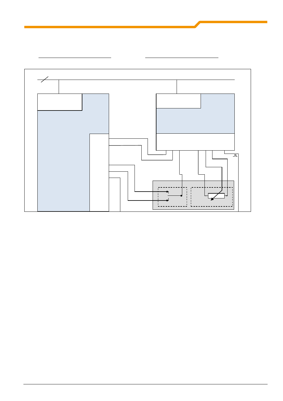
In combination with the SK CU4-24V-
… or SK TU4-24V-… modules instead of the SK CU4-IOE or SK TU4-IOE
Technology Units, the connection to an SK 2x5E series frequency inverter can, for example, be implemented
according to the following pattern.
(Note: Terminal 43 of the SK TU4-24V-
… corresponds to Terminal 44 of the SK CU4-24V-…)
Connection diagram for SK xU4-24V-
… and parameterisation, example
Frequency inverter
SK 205E-.../SK 215E-...
Co
ntro
l terminal b
ar
44
40
.
.
21
22
23
24
.
.
.
L1 - L2/N - L3
115/230/400V
24V mains unit
SK TU4-24V-...
(+ SK TI4-TU-NET)
*
or
SK CU4-24V-...
L1 - L2/N
115/230/400V
24V=
GND
10V=
AGND
0-10V
R
L
0-100%
1/3~ 115/230/400V + PE
Control terminal bar
44* 40 44* ... 11 14 12 B1
Switch
Potentiometer 10kOhm
SK POT1-1
green
brown
white
pink
green
yellow
DIP switch settings:
DIP3 = off, DIP4 = on, DIP5 = off
(Therefore no further parameterisation is necessary)
or
recommended
parameter setting, DIP1-8 = off:
P400 [07] = 1 P420 [02] = 2
P420 [01] = 1 P420 [03] = 26