NORD Drivesystems BU0040 User Manual
Page 30
NORDAC Control and Parameter Boxes
30
Subject to technical alterations
BU 0040 GB-0113
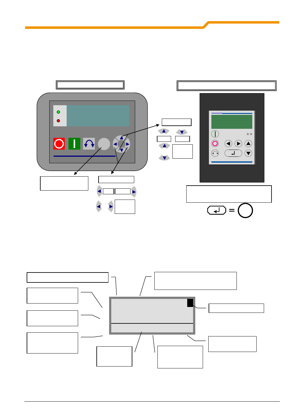
Parameter setup with the ParameterBox
The parameterisation mode is accessed by selecting the menu item >Parameterisation< in level 1 of the
ParameterBox. The parameter level of the connected inverter is accessed with the ENTER key.
The following diagram illustrates the control elements of the ParameterBox for parameterisation.
Screen layout during parameterisation
If the setting of a parameter is changed, then the value flashes until it is confirmed with the ENTER key. In order to
retain the factory settings for the parameter being edited, both VALUE keys must be operated simultaneously. Even
in this case, the setting must be confirmed with the ENTER key in order for the change to be stored.
If the change is not to be stored, then pressing one of the SELECTION keys will call up the previously stored value
and pressing a SELECTION key again will exit the parameter.
P102
PS1
3
Acceleration time
2,90 s
ONLINE
I1
P1
Ready
Note:
The lowest line in the display is used to display the current status of the box and the frequency inverter
being controlled.
DS
DE
NORD
DRIVESYSTEMS
OK
SK PAR-3H
One menu level forward
or
accept parameter value
Selection keys
Value keys
Back
Forward
+
one
menu level
back
Value +
Value -
+
Load
factory
settings
vector
R
DS DE
SK TU3-PAR or SK PAR-2x
The keyboard function is identical to that of
SK PAR-3x
SK TU3-PAR or SK PAR-2H/2E
SK PAR-3H/3E
OK
Parameter set to be edited
(only for dependent parameters)
Parameter to be edited (No.)
Parameter to be
edited (text)
Current parameter
value
Current
ParameterBox
status
Selected
frequency
inverter
Status of the
frequency inverter
Menu structure level
Active parameter
set in frequency
inverter