NORD Drivesystems BU0040 User Manual
Page 54
NORDAC Control and Parameter Boxes
54
Subject to technical alterations
BU 0040 GB-0113
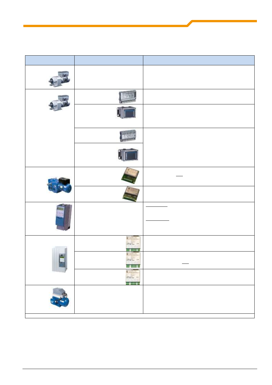
3.2.1.1 Overview
The SK POT1-1 control box can be used with the following devices.
Frequency inverter
series
Option required
Comments*
SK 2x0E
None
DIP switch (2-pole) under central inspection window
(front side of inverter) for analog input 1 / 2to {OFF}
position.
SK 2x5E
SK CU4-IOE
DIP- switch (8-pole) on Technology UnitNo: 1, 2, 3 for
analog input 1in setting {OFF}
SK TU4-IOE
with
SK TIE4-TU-BUS
(optionally with wall-mounting kit)
DIP- switch (8-pole) on Technology UnitNo: 1, 2, 3 for
analog input 1in setting {OFF}
SK CU4-24V-
…
See following section (Control connections) or manual
BU0200
SK TU4-24V
with
SK TIE4-TU-NET
(optionally with wall-mounting kit)
SK 300E
SK CU2-BSC
DIP switch S1-1 (Burden resistor)
in setting {OFF} and
DIP switch S1-2 ("0-10V - Signal processing")
in setting {ON}
SK CU2-STD
DIP switch S1-1 (Burden resistorfor analog input 1)
in setting {OFF}
SK 5xxE
None
Up to size 4
DIP switch AIN1
(Burden resistorfor analog input 1)
in setting {OFF}
Above size 5
DIP switch S1 and S3 (Burden resistor foranalog input 1
and "0-10V signal processing")
to setting {OFF}
SK 700E
SK CU1-BSC
(Similar to illustration)
Set bridge between X3.2-12 and X3.2-13
SK CU1-STD
DIP- Switch (
Burden resistor, analog input
)
to setting
{OFF} and
set bridge between X1.2-12 and X1.2-13
SK CU1-MLT
(Similar to illustration)
DIP switch (Burden resistor, analog input 1)
to setting {OFF}
SK 750E
As for SK 700E
As for SK 700E
* It is assumed that the connection is made to Analog Input 1.