NORD Drivesystems BU0040 User Manual
Page 27
2 Parameter Boxes
– Display and control
BU 0040 GB-0113
Subject to technical alterations
27
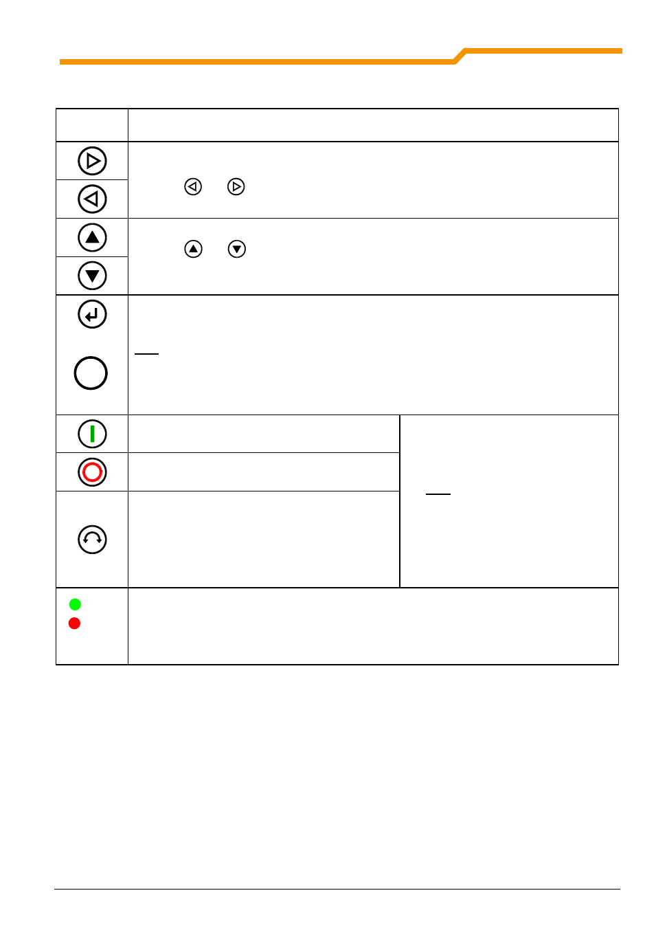
2.2.2.3 Operation
LCD display
Graphic-capable, backlit LCD display for displaying operational values and parameters for the
connected frequency inverter(s) and ParameterBox parameters.
Use the Selection keys to move through the menu levels and within the individual menu items.
Press the
and
keys together to go back one level.
The contents of individual parameters can be altered with the VALUES keys.
Press the
and
keys together to load the default values of the parameter selected.
When controlling the inverter using the keyboard, the frequency setpoint is set using the VALUE
keys.
or
Press the ENTER key to select a menu group or accept the changed menu item or parameter
value.
Note:
If a parameter is to remain, without a new value being stored, then one of the
SELECTION keys can be used for the purpose.
If the inverter is to be controlled directly from the keyboard (not control terminals), then the actual
setpoint frequency can be stored under the Jog Frequency parameter (P113).
START key for switching on the frequency inverter.
Note:
Can only be used if this
function has not been blocked in
parameter P509 or P540.
STOP key for switching off the frequency inverter.
The direction of rotation of the motor changes when
the DIRECTION key is operated. Rotation direction
left is indicated by a minus sign.
Attention! Take care when operating pumps, screw
conveyors, ventilators, etc.
→ You can disable the
key with parameter P540.
The LED's indicate the actual status of the ParameterBox.
DS (
ON
(green))
Device State
The ParameterBox is connected to the power supply and is operational.
DE (
ERROR
(red))
Device Error
An error has occurred in the processing or communication of the data or in
the connected frequency inverter.
DS
DE
OK