Functions, Dig i n 5, Vo + 5 v – NORD Drivesystems BU0040 User Manual
Page 46
NORDAC Control and Parameter Boxes
46
Subject to technical alterations
BU 0040 GB-0113
P1
P2
Functions
In this operating mode the functions
Parameterisation
Control
Display of operating values
are available without restriction and correspond to those of the SimpleBox SK CSX-3H/ -3E.
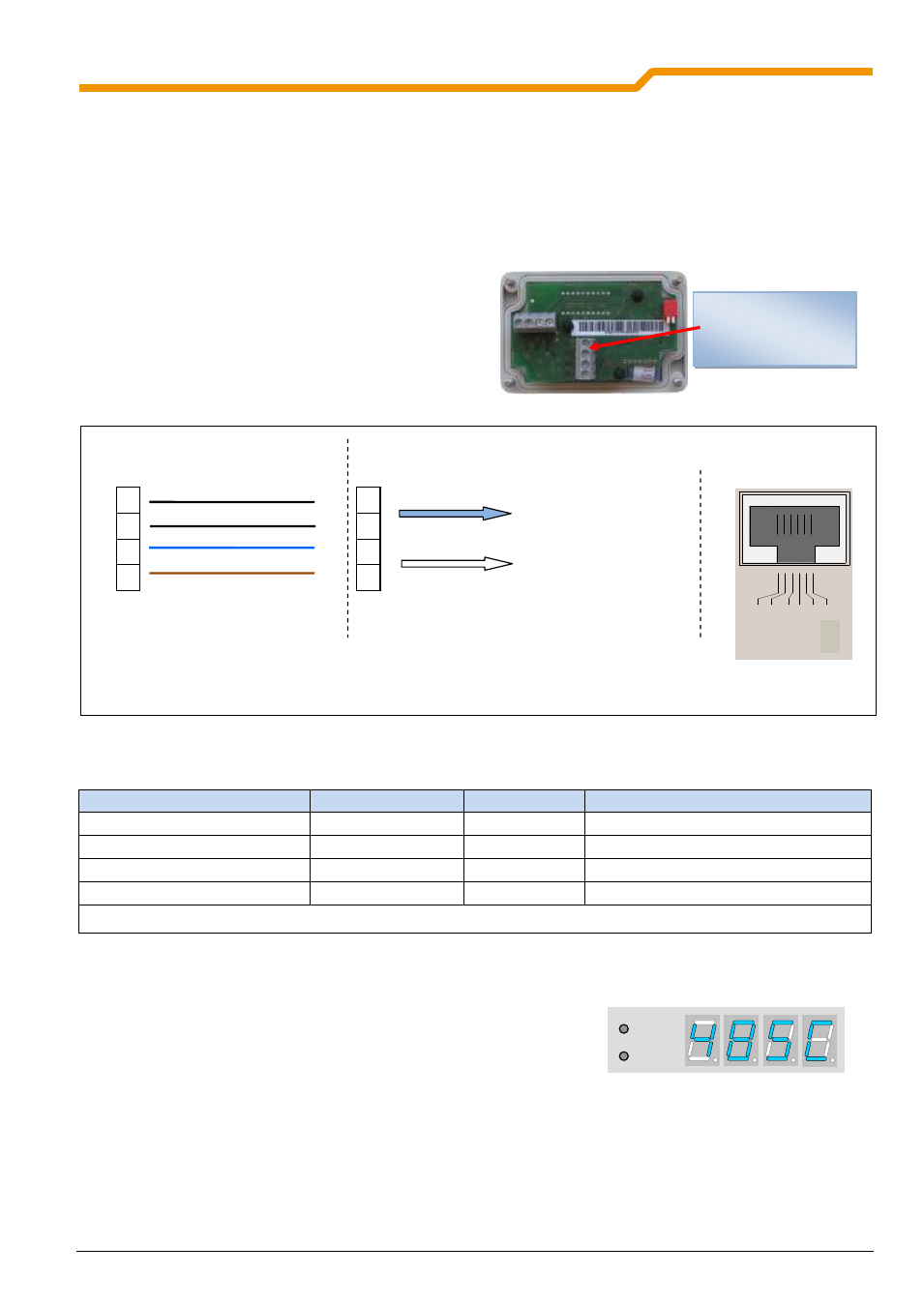
Connections
Connection to the vertical terminal bar is by means of a 4-
wire cable.
An integrated 270
Ω termination resistor is provided for
RS485 communication.
Settings on the frequency inverter
Name
Parameter number
Value
Notes
Control word source
P509
0
Corresponds to default value
Setpoint source(s)
P510
0
Corresponds to default value
USS Baud rate
P511
3 (38400 Baud)*
Corresponds to default value
USS address
P512
0
Corresponds to default value
* Lower baud rates can also be set, however the SK SSX-3A (temporarily) configures the frequency inverter to the setting {3} = 38400Baud, if this was parameterised to the value
<19200Baud. After the mains are switched off at the frequency inverter, the original setting is once again active.
Boot UP display
After switching on, the lettering briefly appears in the display
Operation
Control of the Simple Setpoint Box SK SSX-3A in this mode is identical to that of the SimpleBox SK CSX-3H/ -3E
(see Section 2.2).
Control commands (enable/stop/direction of rotation) and setpoints from the box are only recognised by the
frequency inverter if it has not been enabled from other sources (e.g. digital input of the FI). (Priority switching).
This also means that the drive of the source from which it was started must also be set back to Stop.
Terminal bar
a)
24V
GND/0V
44
40
73
74
24V voltage supply
from FI
b)
RS485 data cable to
frequency inverter
RS485 B (-)
RS485 A (+)
SK SSX-3A
Frequency inverter SK xxxE
44
40
73
74
V
RE
F
1
0
V
A
G
N
D
0
V
A
IN
1
+
A
IN
2
+
A
O
U
T
1
D
IG
I
N
1
D
IG
I
N
2
D
IG
I
N
3
D
IG
I
N
4
V
O
+
1
5
V
D
G
N
D
0
V
11
12
13
14
16
22
23
24
25
42
40
21
D
IG
I
N
5
1
2
3
4
RE
L
2
.2
RE
L
2
.1
RE
L
1
.2
RE
L
1
.1
C
A
N
_
H
C
A
N
_
L
C
A
N
_
G
N
D
nc
C
A
N
_
S
H
L
D
C
A
N
_
G
N
D
nc
C
A
N
_
2
4
V
CA
N
_
H
CA
N
_
L
C
A
N
_
G
N
D
nc
C
A
N
_
S
H
L
D
C
A
N
_
G
N
D
nc
C
A
N
_
2
4
V
RS
4
8
5
_
A
RS
4
8
5
_
B
G
N
D
T
X
D
RX
D
41
V
O
+
5
V
+
5
V
+
2
4
V
RJ12 socket
a), c)
Connection for 485-C mode
a) If available on the frequency inverter
b) Supply via terminal 43 or 44, according to the device 24V
DC
– Supply by separate mains unit is also possible
c) Observe correct voltage (24V
DC
), if necessary, provide the supply voltage to the SK SSX3A separately.
44
24V
DC
40
GND
73
RS485 A(+)
74
RS485 B(-)