KROHNE IFC 090 Converter EN User Manual
Page 71
10/2
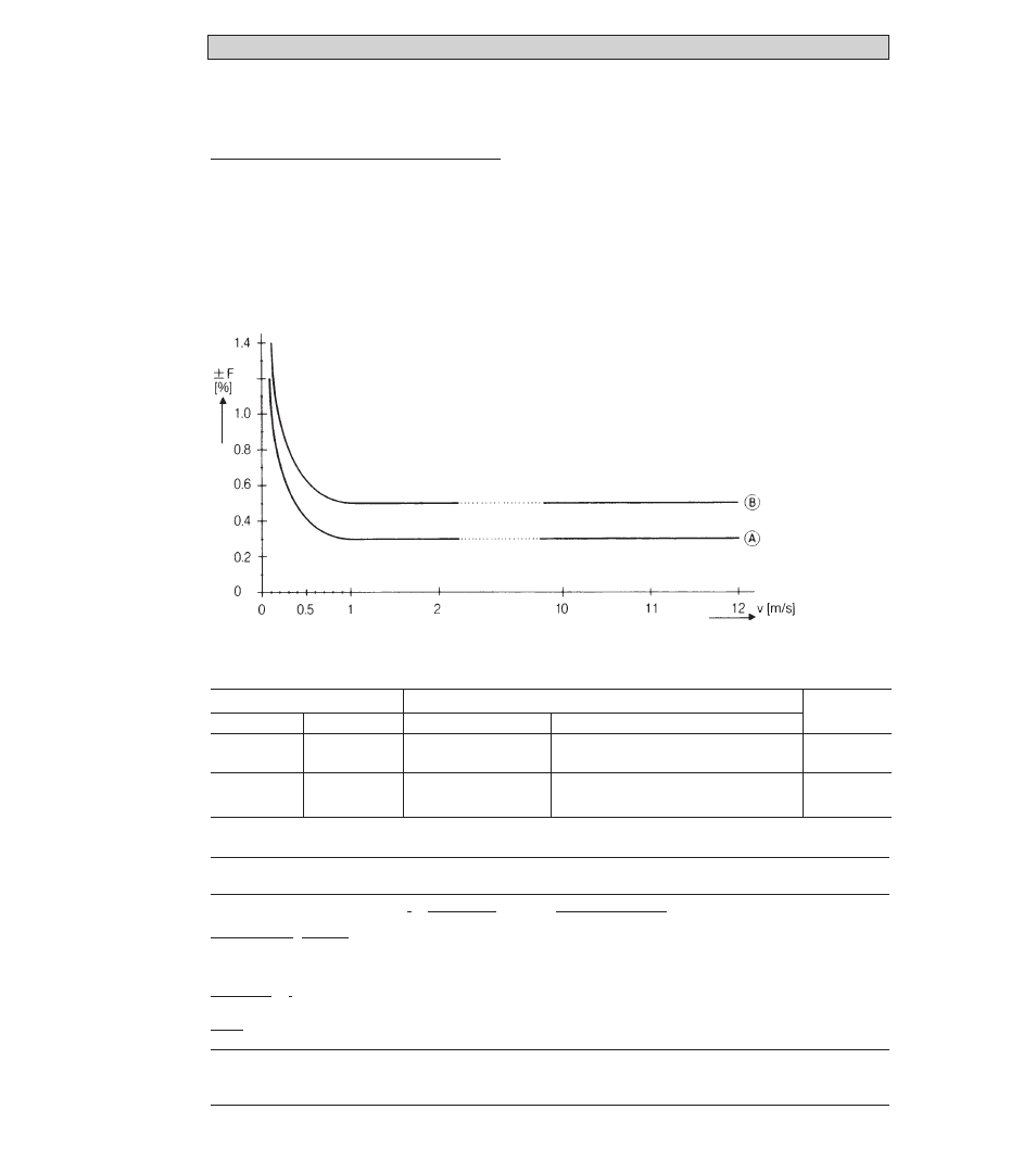
Error limits at reference conditions 10.3
Display, digital values, pulse output
F
maximum error in % of measured value (not typical values)
v
Flow velocity in m/s and ft/s
Reference conditions similar to EN 29 104
Product
water at 10 – 30°C/50 – 86°F
Electrical conductivity
> 300
µ
S/cm
Power supply (rated voltage)
U
N
(± 2%)
Ambient temperature
20 – 22°C/68 – 71.6°F
Warm-up time
60 min
Inlet/outlet runs
10
x
DN/2
x
DN (DN = meter size)
Primary head
properly grounded and centered
Type/Meter size
Maximum error in % of measured value (MV) ...
Curve
DN mm
DN 2.5 – 6(1)
DN 2.5 – 6(1)
≥
DN 10
≥
DN 10
inch
1
/
10
” –
1
/
4
”(1)
DN 2.5 – 6(1)
≥
3
/
8
”
≥
DN 10
v
≥
1 m/s /
≥
3 ft/s
≤
± 0.5% of MV
DN 2.5 – 6(1)
≤
± 0.3% of MV
≥
DN 10
v
<
1 m/s /
<
3 ft/s
≤
± (0.4% of MV + 1 mm/s)
≤
± (0.4% of MV + 0.04 inch/s
≤
± (0.2% of MV + 1 mm/s)
≤
± (0.2% of MV + 0.04 inch/s)
B
D
A
E
Current output
same error limits as above, additionally ± 10
µ
A
Reproducibility and
repeatability
0.1% of MV, minimum 1 mm/s / 0.04 inch/s at constant flow
External influences
typical values
maximum values
Ambient temperature
Pulse output
<
0.003% of MV (2)
0.01
5
% of MV (2)
Current output
<
0.01
3
% of MV (2)
0.025% of MV (2)
Power supply
< 0.02
3
% of MV
0.05
5
% of MV (2)
at 10% variation
Load
< 0.01
3
% of MV
0.02
5
% of MV (2)
at max. permissible load,
see Sect. 10.4
(1) IFM 6080 K and IFS 6000 F (DN 2.5 – 4 and 1/10 – 1/6”) additional error ± 0,3% of MV
(2) All Krohne signal converters undergo burn-in tests, duration minimum 20 hours at varying ambient temperatures
– 20 to + 60°C/– 4 to + 140°F. The tests are controlled by computers.
}
per 1 K / 1.8°F variation
0 1.6 3.2 6.4 32 36 40 v [ft/s]