KROHNE IFC 090 Converter EN User Manual
Page 61
7/10
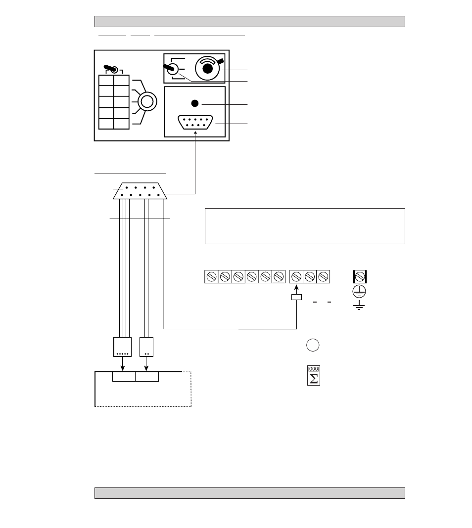
Test of signal converter using GS 8A simulator (option) 7.6
GS 8A operating elements and accessories
+
0
–
B
Plug for field power
supply, 2-pin
C5
Plug for signal cable,
5-pin
D
Switch,
flow direction
H
Socket for H2 plug
on cable Z
H2
Plug of cable Z
L
Power supply ON
P
Potentiometer “zero”
X1
Socket for plug B
on amplifier PCB
X4
Socket for plug C5
on amplifier PCB
Y
Switch,
measuring ranges
Z
Cable between GS 8A
and signal converter
Electrical connection
H2
Z
C 5
B
X 4
X 1
amplifier PCB, see
Sect. 8.9
Connection of milliammeter and
electronic frequency counter
see Sect. 2.6.
10
Outputs/Inputs
Power
U-clamp terminal
B
B
⊥
B2
I+
I
I
⊥
Milliammeter, accuracy
class 0.1, R
i
< 500
Ω
,
range 4-20 mA
Electronic frequency
counter, input resistance
approx. 1 k
Ω
, range
0-1 kHz, time base min. 1
second, see connection
diagrams in Sect. 2.6.
A
a) Switch off power source before
opening the housing !
b) Unscrew the cover from electronic section
using the special wrench.
c) Remove screws R and fold display unit
to side, see illustration in Sect. 8.5.
d) Pull off blue 9-pin plug (X1/X4) from the
amplifier PCB, see Sect. 8.9:
socket X1 field power supply, and socket X4
signal cables.
e) Connect plug B to socket X1 (2-pin) and
plug C (5-pin) to socket X4 (5-pin).
1,25
2,5
5
10
20
320
160
80
40
20
Y
P
D
L
H
L N
1L~ 0L~
} }
binary outputs
and inputs
current
output
(PE)
100-240 V AC
(FE)
24 V AC/DC
(PE protective conductor)
(FE functional ground)
Using GS 8 simulator
Additional adapter is required
between GS 8 and IFC 090 signal converter.
Order No. 2.10764.00.
Warning: Instrument must be properly grounded to avoid personnel shock hazard.