KROHNE IFC 020 Converter EN User Manual
Page 75
Installation and operating instructions IFC 020
11/1
Measuring principle
11
The flowmeter is designed for electrically conductive fluids.
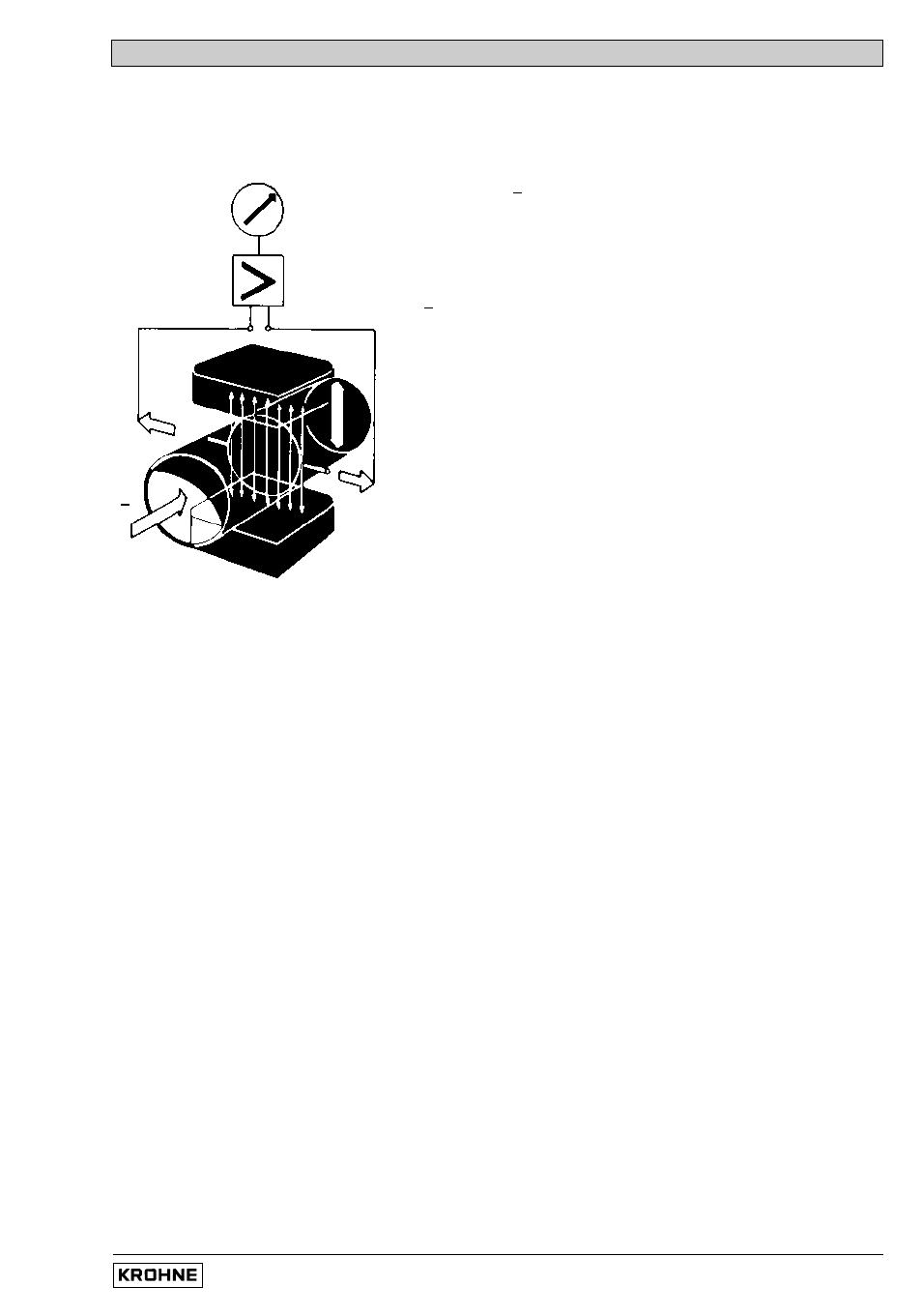
Measurement is based on Faraday’s law of induction, according to which a voltage is induced in
an electrically conductive body which passes through a magnetic field. The following expression
is applicable to the voltage.:
U = K
x
B
x
v
x
D
where:
U = induced voltage
K = an instrument constant
B = magnetic field strength
v = mean velocity
D = pipe diameter
Thus the induced voltage is proportional to the mean flow
velocity, when the field strength is constant.
Inside the electromagnetic flowmeter, the fluid passes
through a magnetic field applied perpendicular to the
direction of flow. An electric voltage is induced by the
movement of the fluid (which must have a minimum
electrical conductivity). This is proportional to the mean
flow velocity and thus to the volume of flow. The induced
voltage signal is picked up by two electrodes which are in
conductive contact with the fluid and is transmitted to a
signal converter for a standardized output signal.
This method of measurement offers the following advantages:
1. No pressure loss through pipe constriction or protruding parts.
2. Since the magnetic field passes through the entire flow area, the signal represents a mean
value over the pipe cross-section; therefore, only relatively short straight inlet pipes
5
x
DN from the electrode axis are required upstream of the primary head.
3. Only the pipe liner and the electrodes are in contact with the fluid.
4. Already the original signal produced is an electrical voltage which is an exact linear function
of the mean flow velocity.
5. Measurement is independent of the flow profile and other properties of the fluid.
The magnetic field of the primary head is generated by a square wave current fed from signal
converter to the field coils.
This field current alternates between positive and negative values. Alternate positive and negative
flowrate-proportional signal voltages are generated at the same frequency by the effect of the
magnetic field, which is proportional to the current. The positive and negative voltages at the
primary head electrodes are subtracted from one another in the signal converter. Subtraction
always takes place when the field current has reached its stationary value, so that constant
interference voltages or external or fault voltages changing slowly in relation to the measuring
cycle are suppressed. Power line interference voltages coupled in the primary head or in the
connecting cables are similarly suppressed.
U
U
D
v
B