3 protection subsystem, 4 [source:]measure subsystem, 5 [source:]input, [source:]output subsystems – KEPCO EL Series Electronic Load Operator Manual P/N 243-1295 Firmware Version 3.22 through 3.41 User Manual
Page 46: 8 status subsystem, 9 system subsystem, Protection subsystem -12, Source:]measure subsystem -12, Source:]input, [source:]output subsystems -12, Status subsystem -12, System subsystem -12
3-12
SERIES EL 062011
3.13.3.3 PROTECTION SUBSYSTEM
This subsystem establishes limits for voltage, current and power.
3.13.3.4 [SOURCE:]MEASURE SUBSYSTEM
This query subsystem returns the voltage, current and power measured at the LOAD terminals.
3.13.3.5 [SOURCE:]INPUT, [SOURCE:]OUTPUT SUBSYSTEMS
This subsystem controls whether the UUT is engaged (on) or disengaged (off) from the load.
3.13.3.6 [SOURCE:]VOLTAGE, [SOURCE:]CURRENT, [SOURCE:]POWER SUBSYSTEMS
These subsystems set the mode and establish setpoints for each mode. Also establish protec-
tion limits and the range of the front panel display (VOLTS, AMPS or KW, respectively) for each
mode.
3.13.3.7 [SOURCE:]RESISTANCE, [SOURCE:]CONDUCTANCE SUBSYSTEMS
These subsystems set the mode and establish setpoints for each mode.
3.13.3.8 STATUS SUBSYSTEM
This subsystem programs the Series EL status register. The electronic load has two groups of
status registers: Operation and Questionable. Each group consists of three registers: Condition,
Enable, and Event.
3.13.3.9 SYSTEM SUBSYSTEM
This subsystem controls various system functions.
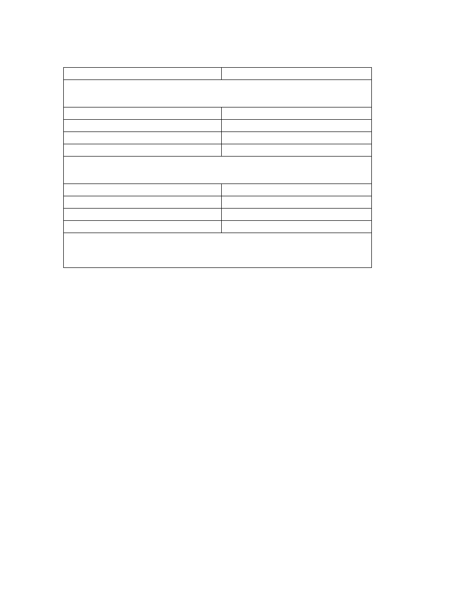
PROTECTION COMMANDS (Terminate command with ? to display the protection setting for that mode.
Exceeding these user-defined protection levels disengages the UUT and displays fault indication (see
PAR. 3.3.1.)
CURRent:PROTection
Set maximum Current level in Amperes
VOLTage:PROTection:OVEr
Set maximum Voltage level in volts
VOLTage:PROTection:UNDer
Set minimum Voltage level in volts
POWer:PROTection
Set maximum load Power in watts
VOLTMETER RANGE COMMANDS (Terminate command with ? to display the range setting. The voltme-
ter range is determined by the lower of: the range setting below and the lowest range that includes the
current VOLT setting.)
SYSTem:RANGe:VOLTage 100V
Set Voltage measurement range 0 – 100V
SYSTem:RANGe:VOLTage 200V
Set Voltage measurement range 0 – 200V
SYSTem:RANGe:VOLTage 400V
Set Voltage measurement range 0 – 400V
SYSTem:RANGe:VOLTage 800V
Set Voltage measurement range 0 – 800V
notation: digits with decimal point and exponent).
NOTE:
If commands that expect a boolean are entered without an argument, the argument is interpreted as 0.
TABLE 3-2. REMOTE OPERATION COMMAND SUMMARY (CONTINUED)
Command
Function