KEPCO EL Series Electronic Load Operator Manual P/N 243-1295 Firmware Version 3.22 through 3.41 User Manual
Page 44
3-10
SERIES EL 062011
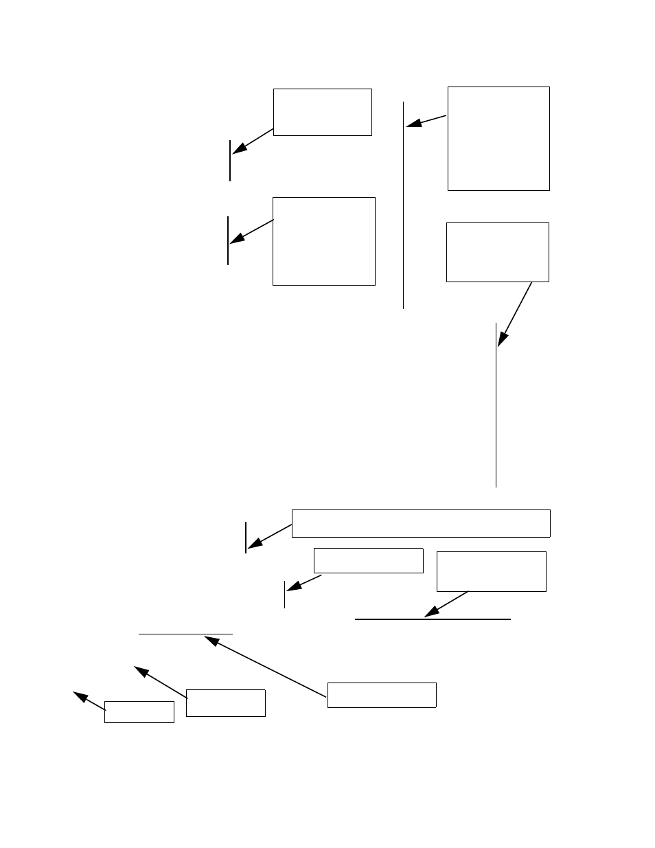
FIGURE 3-2. MASTER/SLAVE START-UP, COMPUTER DISPLAY (SHEET 2 OF 2)
KEPCO, EL 5K-600-200 03-15-2010,A104503,MCB #234 1.219 $ 2010/03/26 12:58:08 $
Chassis Serial Number: A104503
Voltage range : 800V
Current range : 200.0
System damping : 5
PFM damping : 3
Overvoltage limit : 799.0
Undrvoltage limit : 0.000
Overcurrent limit : 600.0
Overpower limit : 6.000
System mode (startup): CURRent
System mode (now) : CURRent
Setpoints
Voltage : 660.0
Current : 0.000
Power : 0.000
Resistance : 1000.
Conductance : 0.001
IP Mode : Static
IP Address : 0.0.0.0
Sub Net : 0.0.0.0
Gateway : 0.0.0.0
DNS Addr : 0.0.0.0
Querying Power FET Module 0 [FET Board # 257 in position 0< 0>]
Found Ser# 257 at position 0 of 1
Querying Power FET Module 1 [FET Board # 258 in position 1< 0>]
Found Ser# 258 at position 1 of 2
Querying Power FET Module 2 [FET Board # 259 in position 2< 0>]
Found Ser# 259 at position 2 of 3
Querying Power FET Module 3 [FET Board # 260 in position 3< 0>]
Found Ser# 260 at position 3 of 4
Querying Power FET Module 4 [FET Board # 261 in position 4< 0>]
Found Ser# 261 at position 4 of 5
Querying Power FET Module 5 [FET Board # 262 in position 5< 0>]
Found Ser# 262 at position 5 of 6
Querying Power FET Module 6
Querying Power FET Module 6
Querying Power FET Module 6 ZYX
Discover Slaves
9
Setting serial # 222 as slave #0
8
Setting serial # 223 as slave #1
7654321
N MCB-Serial Amps Volts Kwatts Ilast Eng Md Setpt Iover Vover Vundr Pover
Master 630 660 15 0 0 2 0 600000 799000 0 6000000
0 222 210 660 5 0 0 0 0 0 0 0 0
1 223 210 660 5 0 0 0 0 0 0 0 0
46
Current EL Load
User Settings
Note: This same
information can be
displayed at any time
by entering the SCPI
command:
SYST:SETTING?
User protection
settings (values
shown are for no
user protection).
User operating
parameter settings
(values shown are for
no current draw at
turn on). Note: Each
parameter is retained
by Mode and is
stored in non-volatile
memory.
Load Dialog During
Process of
recognizing Power
FET Modules found
By Master Control
Board.
Testing for additional Power FET Modules and seeking possible
connections to slave Loads.
Discovering Slave Loads
found by Master Load
Master Control
Board Serial Nos.
Master boot
time (Seconds)
Load System Current
Voltage and Power Limits
Load System overcurrent,
overvoltage, under voltage,
overpower Limits
(mA, mV, mV, mW)