HT instruments SIRIUS89N User Manual
Page 121
SIRIUS89N
EN - 119
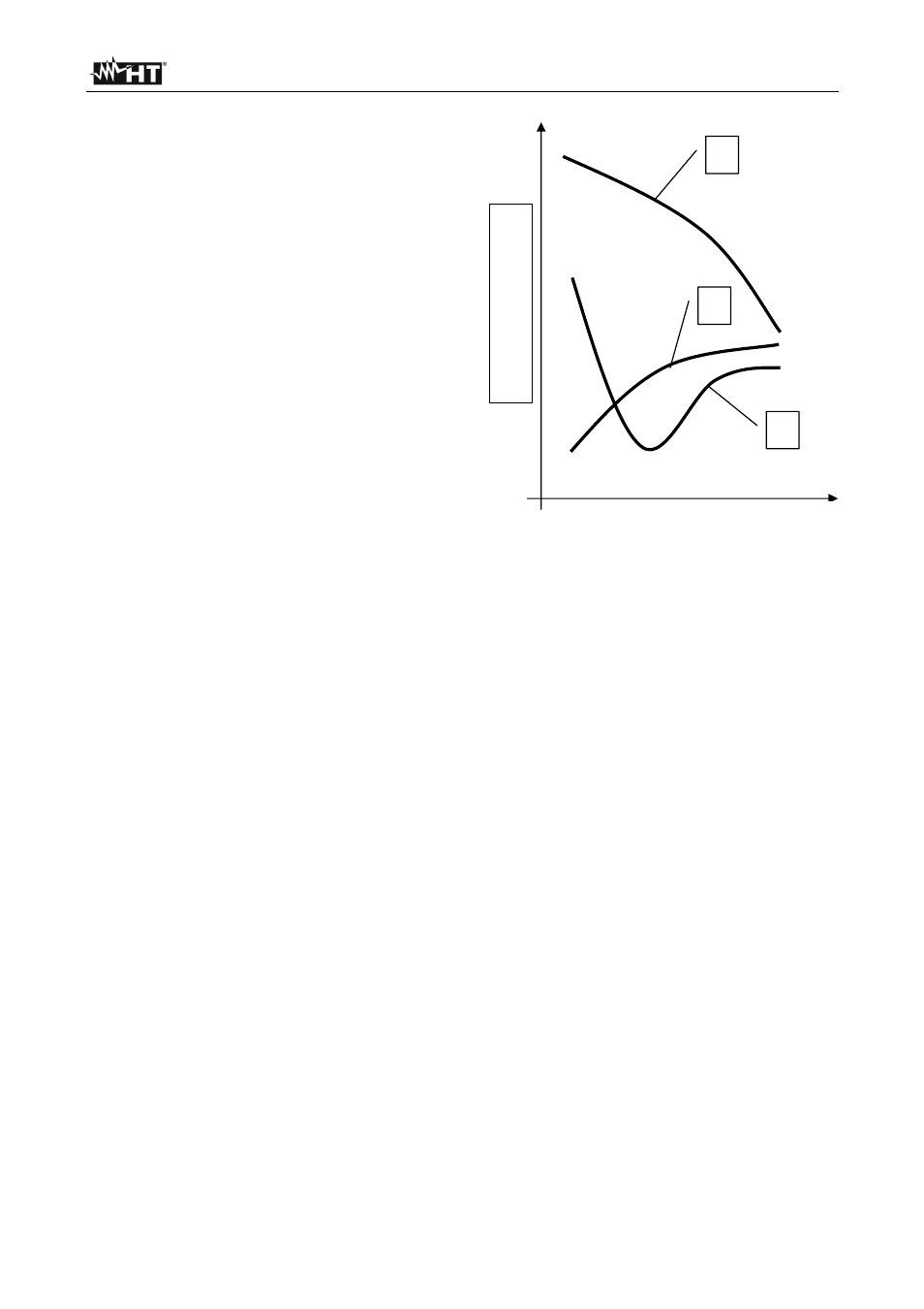
The measuring method allows to define the
specific resistance up to the depth
corresponding approximately to the distance
“
a” between the rods. If you increase the
distance “
a” you can reach deeper ground
layers and check the ground homogeneity.
After several
ρ measurements, at growing
distances “
a”, you can trace a profile like the
following ones, according to which the most
suitable rod is chosen:
Curve1: as
ρ decreases only in depth, it’s
possible to use only a rod in depth.
Curve2: as
ρ decreases only until the depth
A, it’s not useful to increase the depth of the
rod beyond A.
Curve3: even at a superior depth,
ρ does not
decrease, therefore a ring rod must be used.
APPROXIMATE EVALUATION OF THE CONTRIBUTION OF INTENTIONAL RODS (64-
12 2.4.1)
The resistance of a rod Rd can be calculated with the following formulas (
ρ = medium
resistivity of the ground).
a) resistance of a vertical rod
Rd =
ρ / L
L= length of the element touching the ground
b) resistance of an horizontal rod
Rd = 2
ρ / L
L= length of the element touching the ground
c) resistance of linked elements
The resistance of a complex system with more elements in parallel is always higher
than the resistance which could result from a simple calculation of elements in
parallel, especially if those elements are close and therefore interactive. For this
reason, in case of a linked system the following formula is quicker and more effective
than the calculation of the single horizontal and vertical elements:
Rd =
ρ / 4r
r= radius of the circle which circumscribes the link.
1
2
3
Earth rods distances "a" (m)
Resistivity
(Ω
m)