Main circuit board – Fire-Lite MRP-2001C PRE-ACTION/DELUGE CONTROL PANEL User Manual
Page 10
10
MRP-2001 Series Manual — P/N 53040:D 12/15/2010
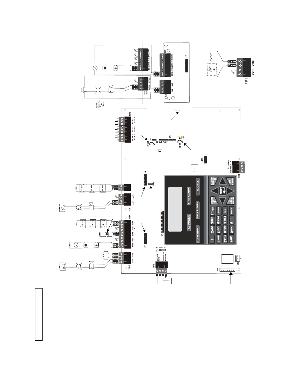
Main Circuit Board
6
6
TB6
Z
O
N
E
6
S
W
1
T
B
4/
T
B
6
1
/6
2
3
5
4
A
A
A
A
Dummy load a
ll unused cir
cuits
with 4.7K
, ½ watt End-
of-Line
res
istor
s
S
ty
le Z
(Class A)
N
A
C
Style D
(Cla
ss
A) ID
C
CAC-
5X
C
lass A C
onve
rt
er Mod
u
le
3 Prog
ramm
able R
elays
Non
supe
rvi
se
d r
el
ay
co
nta
cts
Co
nta
ct Ra
tin
gs
2
.0
am
ps @ 3
0 V
DC (re
sistive
)
0
.5
am
p @ 3
0 V
A
C
(
re
sis
tiv
e)
Co
nta
cts
sh
ow
n b
elo
w in
n
or
m
a
l
co
nd
itio
n (A
C po
we
r with n
o a
lar
m,
tr
ou
ble,
or
su
per
visor
y a
ctivity)
A Fa
il
Saf
e
Tr
ou
bl
e
re
la
y
switche
s to
the
NC po
sition
d
ur
ing
tr
ou
bl
e c
o
nd
ition
s an
d
un
de
r
lo
ss of
al
l p
o
w
e
r.
(*
Facto
ry d
e
faul
t r
ela
y pr
og
ra
m
m
in
g)
Al
ar
m*
T
roubl
e*
S
upe
rv
is
or
y*
Cla
ss A
Conver
ter
Mod
u
le
R
emo
ve
ju
m
per
JP
43
to
dis
a
bl
e G
ro
un
d F
a
ult
Dete
ct
io
n
c
ircui
t (
on
ly with
ap
pr
ov
a
l of
AH
J)
C
ut th
is
jum
per
to su
per
vise
the
4X
TM
F mo
du
le
whe
n
in
sta
lle
d (see
J4
& J5
)
Cut
this jum
per
to
en
ab
le
Su
pe
rvi
so
ry
Re
la
y
w
he
n 4X
TMF
mo
d
ule
is insta
lle
d
A
u
xilia
ry
Tr
ou
bl
e Inp
u
t
K
iss-
off L
E
D
ANN
-S
EC
op
tion
card
conn
ect
o
r
Bat
tery
24 VDC, supe
rvi
se
d
,
non
power-
limit
ed
26
A
m
p Ho
ur
maximum
B
a
sic System Connections
Power Supply Connector
For
mor
e
s
pecific UL w
iring
in
fo
rmat
ion,
r
e
fe
r to pa
ge
35.
Im
por
ta
nt!
Re
moving Gro
und Fault
Disa
b
le
Jumper JP
43 voi
d
s
UL/
N
FPA St
yl
e/
Clas
s
ind
entific
at
io
ns
for circuits.
Re
move
ju
mper
JP43
on
ly
wit
h th
e
appro
va
l o
f th
e local AHJ
(Aut
hority Having Jur
isdict
ion).
Sp
ecial Ap
plica
tion
D
C
Power Outp
ut
s 24 VDC)
N
onsuper
vi
se
d, powe
r-limit
ed
circuit
s
Supe
rvise
wit
h a power
supe
rvision rela
y
EOL
R
-1
R
ese
tt
abl
e
P
o
wer - 24 VDC fil
ter
ed,
power-
limit
ed,
Cla
ss 2 (0.
5
amp
maximum) to
smoke det
ecto
rs
(I
DC).
Supe
rvise
wit
h
power
sup
e
rvision
relay EOL
R
-1.
N
onreset
table
or
Reset
table
Po
w
er
Ju
mper select
able by JP
31,
2
4
VDC
filter
ed, p
o
wer-li
m
ite
d
, Class 2
(
0
.5
amp
maximum).
Sup
e
rvise with
po
wer
su
pvervision r
e
lay EO
LR-1.
Non
reset
ta
ble
Power suit
able
f
o
r powe
ring smoke
det
ecto
rs.
C
onf
igure
TB9
, Termin
a
ls
1
& 2 as
R
ese
tt
abl
e
or
N
onreset
table Po
w
er.
•
R
eset
tabl
e
P
o
wer - jumpe
r
JP
31 pins 2
& 3
•
N
onr
esett
able
Po
wer
- jumper
JP3
1
p
ins
1 & 2 (as
sho
w
n)
4 3
2 1
{
{
Ou
tpu
t Cir
cuit #
1
NA
C
O
u
tpu
t Circu
it
#3
N
A
C
P
u
sh switch d
o
wn to
up
gr
ad
e so
ftw
ar
e
IDCs
1 t
h
rough 6,
St
yl
e
B (Cl
a
ss B) (Sup
ervi
sed,
Power
-Li
mit
ed,
Cl
ass
2)
(
S
ee St
yl
e D
ill
u
st
rat
ed
near
ri
ght
e
dge of
board.
)
4.
7Kohm
, ½
watt
End-
of
-Li
ne Resi
stor
PN 71252
Ini
tiating De
vi
ce
Circui
ts
rp2001layout.wmf
N
o
rm
a
lly
Open
Wa
te
rf
lo
w
D
evic
e
s or
Pr
essu
re
Swi
tches
Input
I
DC
Wa
te
rf
lo
w
C
irc
ui
t #6
Ou
tp
ut Cir
cu
its - TB5
& TB7
S
pe
cia
l Ap
p
lica
tio
n
P
o
wer
In
this e
xam
ple
NAC O
u
tp
ut
Ci
rc
uit
s #1
, #
3
, & #
4
, Style
Y
(Class
B)
(
S
up
er
vise
d,
Po
we
r-L
imite
d, Class 2
)
NA
C
Ou
tp
u
t Cir
cuit #2
(
R
ele
a
sing
) is
S
tyle
Y
(
Cla
ss
B
)
(S
up
er
vi
sed
, N
onpo
w
e
r-
Li
mi
te
d,
C
la
ss 1)
3
.0 am
p m
a
x. pe
r ci
rcu
it.
(S
ee Styl
e
Z
ill
ustr
a
te
d n
e
ar
r
igh
t e
d
ge
o
f bo
ar
d.
)
4.7
K
oh
m
, ½
w
a
tt En
d-
of-
L
in
e R
esist
or
PN
7
1
25
2
Ou
tp
u
t
Circu
it #2
Re
le
as
in
g
In
pu
t ID
C
Circu
it #1
po
la
ri
ze
d
be
ll
po
lar
iz
ed
str
obe
po
la
rized
ho
rn
sm
ok
e
de
tec
tor
pu
ll
sta
tion
heat
de
te
ct
or
m
anu
al
re
le
as
e
N
o
rm
a
lly
Open Tamper
or
Pr
e
ss
u
re
S
w
itches
In
pu
t IDC
Su
pe
rvi
so
ry
Circu
it #5
Out
put
Circu
it
#4