Yokogawa DA100 User Manual
Page 69
IM DA100-01E
3-10
Temperature Measurement Using TC
DC voltage input for DC voltage measurement substitutes for this.
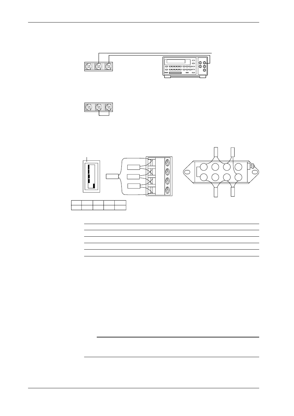
DC Current measurement
Apply the 20mA to channel 3
+
–
Input terminal
(CH3)
DC Current Generator
Short circuit between “+” and “–” terminal in channel 2
+
–
Input terminal
(CH2)
Strain measurement
Wire the strain gauge or the bridge box to the channel 2.
Jumper setting switch
ON
OFF
No.1
No.2
No.3
No.4
No.5
A(+)
B(L)
C(-V)
D(H)
DU500-12/DU500-13
DU500-14
No.1
OFF
No.2
OFF
No.3
OFF
No.4
OFF
No.5
ON
1
2
3
4
5
6
7
8
R4
R2
R3
R1
R2
R4
R3
R1
To R1 to R4, connect resisters with the specifications described below.
Calibration
Resisters R1, R2, R3
Resister 4
Accuracy
ZERO
120.000
120.000
±0.005%, ±0.3ppm/°C
2k SPAN
120.000
119.521
±0.005%, ±0.3ppm/°C
20k SPAN
120.000
115.294
±0.005%, ±0.3ppm/°C
200k SPAN
120.000
80.000
±0.005%, ±0.3ppm/°C
Voltage or Current Output Using Retransmission Module
When clibrating the retransmission module by confirming the output value, connect a DMM (a
product corresponding to HP3458A) to the terminal to be calibrated.
Calibration Procedure
1 Connect the equipment as described above.
2 Verify that the calibration conditions are satisfied.
3 Start the DAQ Software 32.
4 Start the calibration program by clicking the [Calibration] icon.
5 Carry out the calibration operations (A/D adjustment) conform the DAQ Software 32 User’s
Manual (IMDP12013-62E).
Note
Instead of operating the DAQ Software 32, calibration can also be carried out by communication interface
using the [XZ] command. For details concerning this command, refer to the User’s Manual “Data
Acquisition Unit Communication Interface”, IMDA100-11E.
3.4 About Maintenance and Calibration