Installation and wiring • four-gauge method, Terminals, 6 connecting the signal lines – Yokogawa DA100 User Manual
Page 40
IM DA100-01E
2-19
2
Installation and Wiring
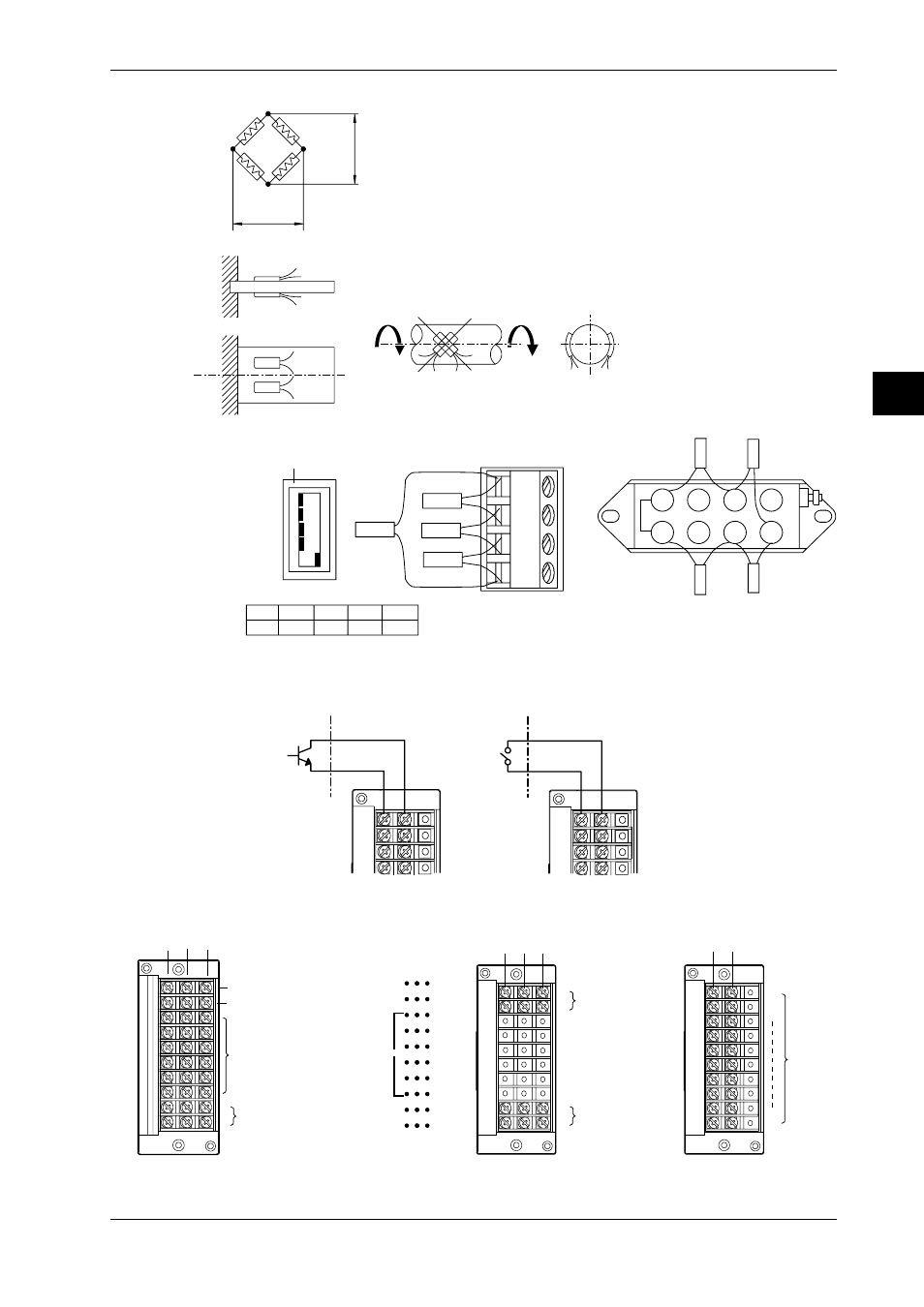
• Four-gauge method
Jumper setup switch
DU500-12/DU500-13
DU500-14
ON
OFF
No.1
No.2
No.3
No.4
No.5
A(+)
B(L)
C(-V)
D(H)
No.1
OFF
No.2
OFF
No.3
OFF
No.4
OFF
No.5
ON
Rg1
Rg2
Rg4
Rg1
Rg2
Rg3
E
e
Rg1, Rg3
Rg2, Rg4
Rg1
Rg3
Rg1
Rg3
Rg4
Rg2
Rg1, Rg2
Rg3, Rg4
Rg3
Rg4
R = fixed resistor
r = resistance of leadwire
Rg = resistance of strain gauge
e = output voltage developed across bridge
E = voltage imposed across bridge
1
2
3
4
5
6
7
8
Rg2
Rg1
Rg3
Rg4
Wiring Pulse Input Signal Lines (to Pulse Input Module)
- +
- +
Open collector
TTL open collector
Contact
Channel1
Channel2
Channel3
Channel4
Channel1
Channel2
Channel3
Channel4
Wiring Alarm Output SIgnal Lines (to DI/DO and Alarm output modules)
Terminals
NO C NC
Failure output (transfer-contact)
REM
CHART
FAIL
ALM
1
ALM
2
NO
NO
1
3
5
7
9
11
NO
NO
C
C
C
C
C
C
C
C
C
C
NC
NC
2
4
6
8
10
12
NC
NC
cannot be used
Remote control signal input
(12 contact terminals) for
only with math (/M1) option
Terminal arrangement
1
2
Alarm output
(transfer-contact)
NO C
1
2
4
NC
3
Alarm output
(transfer contact)
Alarm output
(transfer contact)
DT200-11
DT100-11
NO C
1
2
10
Alarm
output
(make
contact)
DT200-21
2.6 Connecting the Signal Lines