3 how to connect the input/output modules, How to connect the input/output modules -4, Warning – Yokogawa DA100 User Manual
Page 25: Connecting method
IM DA100-01E
2-4
2.3
How to Connect the Input/Output Modules
WARNING
When connecting the Input/Output modules, make sure to turn OFF the
power to the DA100/DS400/DS600 to prevent an electric shock or damage
to the instrument.
Setting the Unit Number of each Subunit (only for the DA100 Expandable type)
When connecting subunits to the DA100 Expandable type, it is necessary to assign a distinctive
unit-number to each subunit. This number can be selected from 0 to 5 (the setting 6 and up will
not be recognized) and is set, as shown in the figure below, by a setting switch (rotary dipswitch).
Note
When you connect an input module at the location of the setting switch, the switch can not be operated
anymore. Therefore, make sure you set the switch before connecting any input module there. It is
convenient for confirming unit numbers to write each unit number setting on a dented part located on the
top of DS600 subunit or on the left side of DS400 subunit.
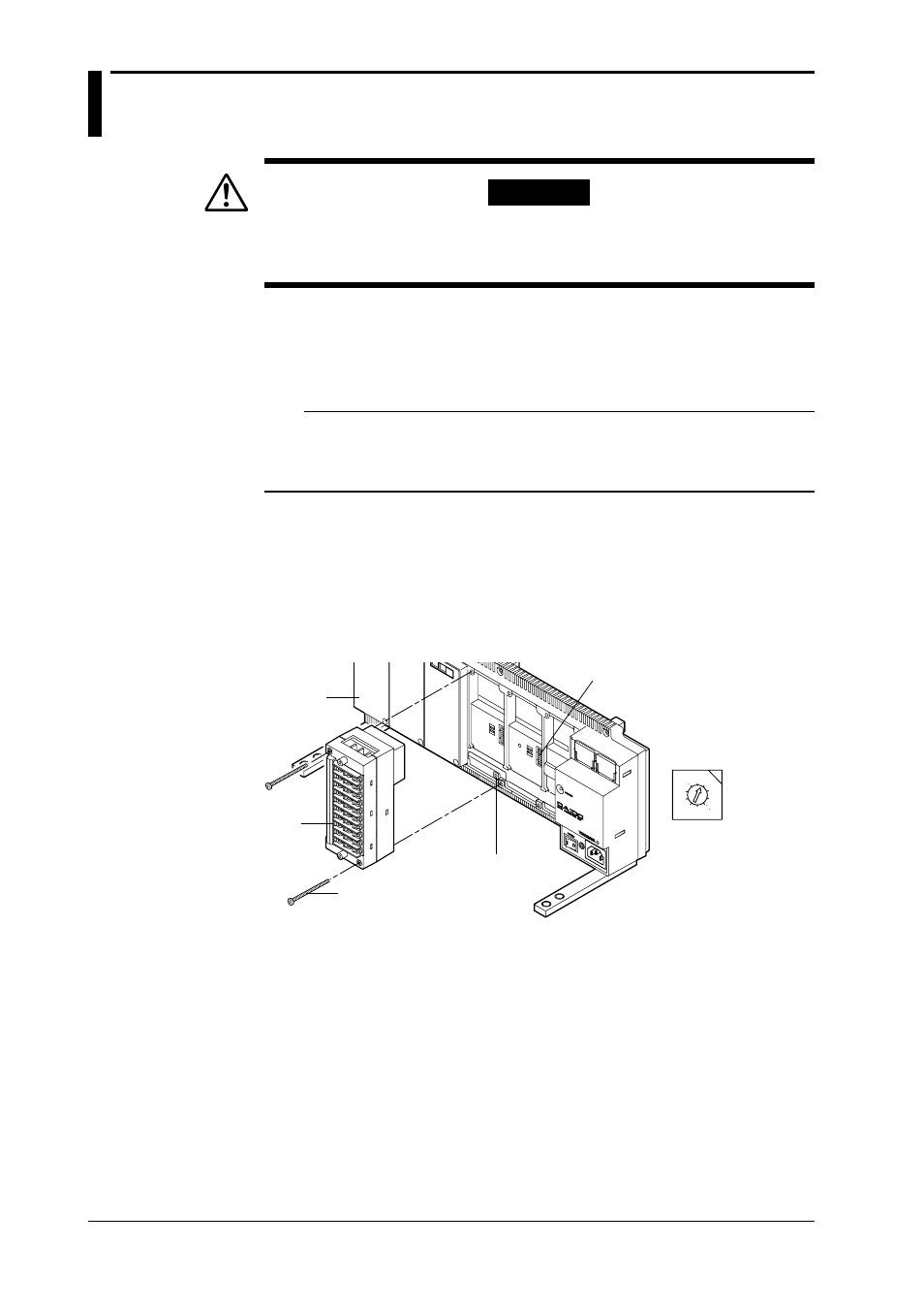
Connecting Method
1 Verify that the power to the DA100/DS400/DS600 has been turned OFF.
2 Remove the cover of the location where the module will be connected. Do not remove any
cover of locations where no module will be connected.
3 Hold the input unit so that the male part of the connector at the back side of the input unit
matches the female part of the receiving connector. Then connect the unit.
4 Fasten the input unit by fastening the two accessory M3 screws.
0 1
2
3
45
6
7
8
9
Module connector
Screws to fasten the module
Input
module
Switch for setting
the unit number
• Switch for setting the
unit number
(settable from 0 to 5)
Cover