Warning, Caution – Yokogawa DA100 User Manual
Page 48
IM DA100-01E
2-27
2
Installation and Wiring
DA100/DS400/DS600(when using DC power terminal connecter)
This applies only to products with power supply 2 suffix code.
Follow the warnings below to avoid electric shock or damaging the instrument.
WARNING
• Connect the power wires after checking that the power supply is turned
off to prevent electric shock.
• To prevent fire, use wires with cross sectional area of 0.3mm
2
(22AWG)
or more.
CAUTION
• If you connect the + and - terminals in reverse on the DA100/DS400/
DS600, the internal fuse will be blown (You cannot replace the fuse by
yourself. The instrument needs servicing in this case). If there is a
possibility of reversing the polarity, insert a fuse (rating shown below) in
the wiring. This will lower the chances of blowing the internal fuse.
Fuse: 250 V/T2.5 A to T4A (time lag), 20 mm glass tube fuse,
I
2
t = 12.5 to 32
(Recommended: A1350EF (250 V/T2.5 A, I
2
t=12.5: SCHURTER:
FST0034.3121))
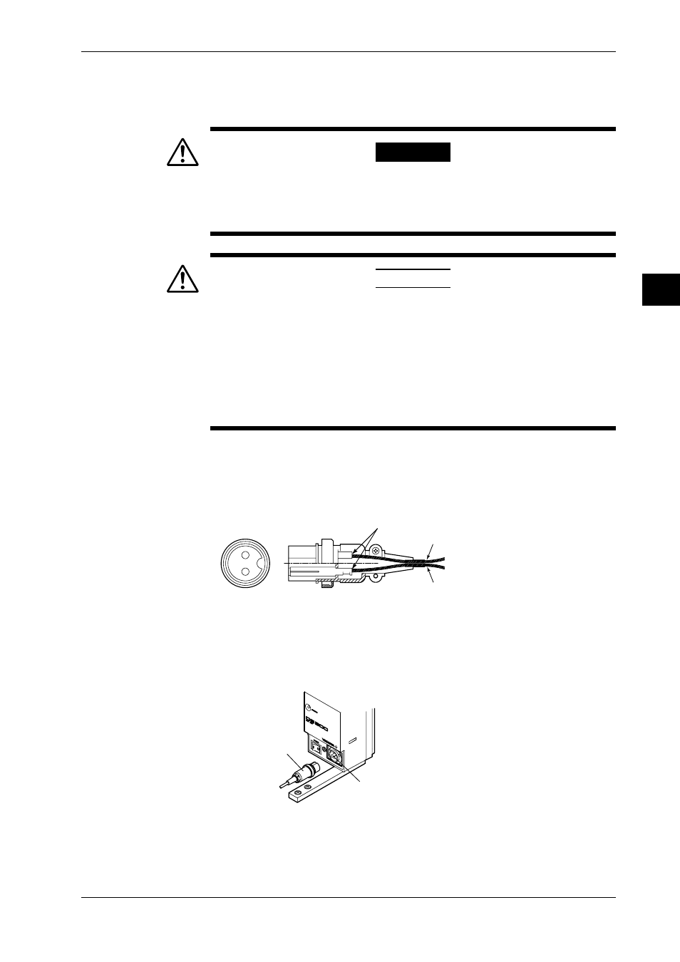
Connecting procedure
1. Check thst the power switch is turned off.
2. Connect the accessory DC power terminal connector (part No. A1105JC) to the power wire
and the DA100/DS400/DS600. Use a power wire with a cross sectional area of 0.3 mm
2
(22AWG) or more.
21
Soldering
- (0 V DC)
+ (10 to 32 V DC)
DA100/DS400/DS600
Rated supply voltage: 12 to 28 V DC
Operating supply voltage: 10 to 32 V DC
Power consumption: About 25 VA max.
• DA100/DS400/DS600: DC power supply model
DC power terminal
connector
DC power
terminal
2.8 Connecting the Power Cord and Turning the Power ON/OFF