Anti-noise measures for the da100, Anti-noise measures: applications – Yokogawa DA100 User Manual
Page 54
IM DA100-01E
2-33
2
Installation and Wiring
Anti-Noise Measures for the DA100
Pulse-width modulation (PWM) A/D converter
This instrument employs an in-house developed PWM A/D converter. Its two main features are:
· Superior linearity and stability achieved by the feedback effect;
· Excellent noise rejection because of the integral A/D converter.
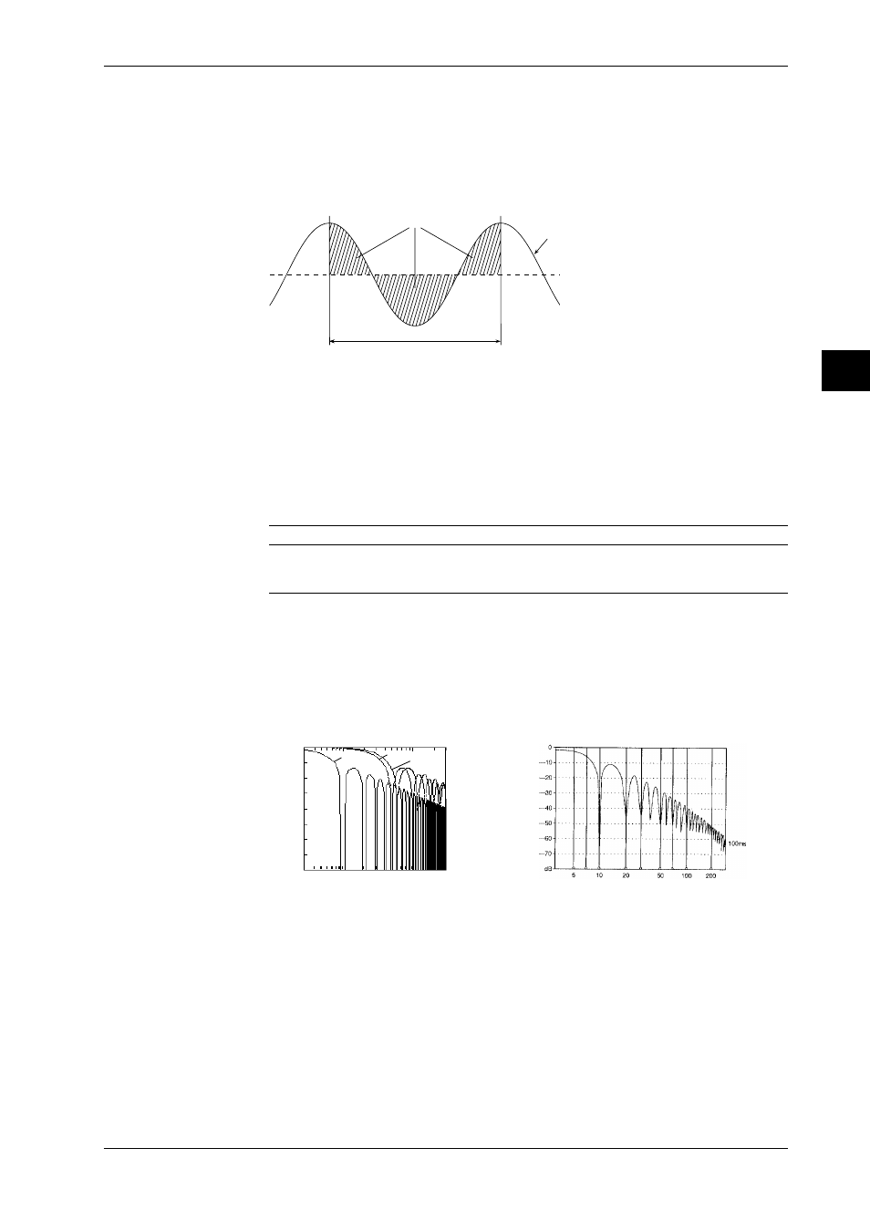
If the integral time and noise cycle are equal, the shaded portions on the plus and minus sides
balance each other and the average value becomes zero.
Balance each other
integral value
DC voltage (average value)
Input voltage (instantaneous value)
Normally, an integral time of 20ms (50Hz) or 16.7ms (60Hz) is selected depending on the
commercial power supply frequencies. A 100-ms integral mode is added to the DA100 to achieve
superior noise rejection. However, when using the 100ms setting, the smallest measurement
interval is longer than in case of the 20ms or 16.7ms setting. The integral effect enables the PWM
A/D converter to perform the following two functions.
· Rejection of frequency determined by the reciprocal of the integral time and frequencies which
are whole multiples of that frequency;
· First-order lag filter provided with cut-off frequency proportional to the reciprocal of the integral
time.
The following table compares the integral times of 16.7ms, 20ms and 100ms.
Integral time
Rejection frequency
Cut-off frequency
Remarks
16.7ms
n
×60Hz
approx. 19Hz
for 60Hz
20.0ms
n
×50Hz
approx. 16Hz
for 50Hz
100.0ms
n
×10Hz
approx. 3.2Hz
for both 50Hz/60Hz
n=1,2,3...
As shown in the table, the merit of 100.0-ms integration is not only that it applies to both 50 and
60Hz, but also that it provides a low cut-off frequency as the first-order lag filter and improves
the noise rejection ability.
The following figure shows the calculation values of the NMRR for three integration times and an
example of actual measurement of the NMRR for a 100-ms integral signal.
• Calculated values of NMRR
• Example of actual measurement of
NMRR
(100ms)
0
-20
-40
-60
-10
-30
-50
-70
5
10
20
50
100
200
Frequency (Hz)
dB
16.7ms
20.0ms
100ms
Frequency (Hz)
Noise Filter
This instrument is equipped with a low-pass filter (cutoff-frequency of 10Hz (for both 50/60 Hz),
50Hz,60Hz) which functions as a way of noise rejection. Also exponential averaging functions as
a noise filter.
Anti-Noise Measures: Applications
Practical Measures
• Reducing noise itself
The basics of this practical measures dictates using the instrument in conditions where noise is
suppressed as much as possible.
· for power lines: an increase of impedance;
Separate the power lines for noise source equipment (inverter, thyristor, etc.) from those for the
measuring instrument.
2.9 Countering Noise