Yokogawa DA100 User Manual
Page 41
IM DA100-01E
2-20
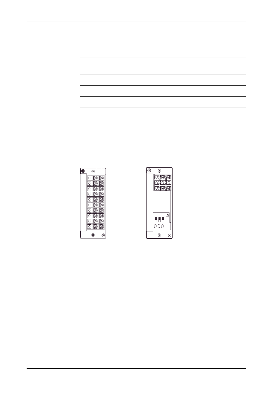
Connecting the Retransmission Signal Lines (Retransmission Module)
Processing of Faulty Data
You cam set the output value that corresponds to abnormal measured balues, computed values,
and communication input value using the dip switch of the retransmission module.
Output Type
Output Value
Switch1
Switch2
Switch3
Approx. 0 V (0.05 V or less)
ZERO
OFF
OFF
–
or approx. 0 mV (0.15 mA or less)
-5%
-OVER
ON
OFF
–
(0.8 V or 3.2 mA)
+110%
+OVER
OFF
ON
–
(5.4 V or 21.6 mA)
Value immediately before
Previous value
ON
ON
–
the faulty data occurence
Data are processed as faulty data in the following cases:
• When the power of the expanded model main unit switches OFF.
• When the measurement channel that is retransmitting experiences the following:
The module of the corresponding measurement channel is removed from the unit.
The power of the unit to which the corresponding channel is connected is removed.
Terminals
Channel 1
- +
Channel 2
Channel 3
Channel 4
Channel 5
Channel 6
Channel 7
Channel 8
Channel 9
Channel 10
- +
Channel 1
SW1
SW3
ON
OFF
SW2
Channel 2
DT500-11
DT500-21
2.6 Connecting the Signal Lines