Yokogawa DA100 User Manual
Page 45
IM DA100-01E
2-24
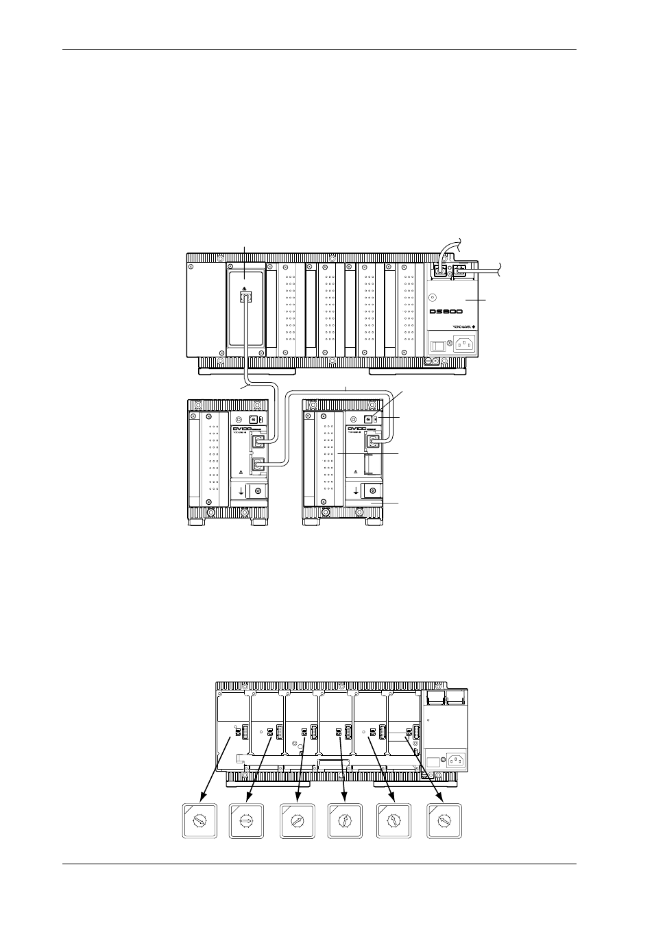
Connecting Extension Bases to an Extension Module
Verify that the power of the DS400/DS600 has been turned off before connecting the extension
module/extension base.
Mount the extension module onto a stand-alone model of the DA main unit or an expandable
model of the DS sub-unit. Wire the module to the extension base with an extension cable. You
can wire one extension module to one of these units. In addition, you can wire a maximum of
three extension bases at the same time to the extension module. It is not possible, however, to
wire extension bases in such a manner that the total sum of modules already mounted on the main
unit/sub-unit and the extension bases being wired exceeds the maximum number of modules (six
for the DA100 main unit, four for the DS400 sub-unit and six for the DS600 sub-unit) allowed for
mounting on the main unit/sub-unit.
Either a 10-channel universal input module (DU100-11 or DU100-12) or a 10-channel DCV/TC/
DI module (DU200-11 or DU200-12) can be mounted onto each extension base.
CH
1
CH
2
CH
3
CH
4
CH
5
CH
6
CH
7
CH
8
CH
9
CH
10
b -/B +/A
CH
1
CH
2
CH
3
CH
4
CH
5
CH
6
CH
7
CH
8
CH
9
CH
10
b -/B +/A
CH
1
CH
2
CH
3
CH
4
CH
5
CH
6
CH
7
CH
8
CH
9
CH
10
b -/B +/A
CH
1
CH
2
CH
3
CH
4
CH
5
CH
6
CH
7
CH
8
CH
9
CH
10
b -/B +/A
P O W E R
STATUS
1 0 0 - 2 4 0 V 5 0 / 6 0 H z 7 0 V A M A X
SUB UNIT
EXTENDER I/F
I/F
POWER
ADDRESS TERMN
ON
OFF
I/F
1
2 3 4
5
6
78
9
0
CH
1
CH
2
CH
3
CH
4
CH
5
CH
6
CH
7
CH
8
CH
9
CH
10
b -/B +/A
POWER
ADDRESS TERMN
ON
OFF
I/F
1
2 3 4
5
6
78
9
0
CH
1
CH
2
CH
3
CH
4
CH
5
CH
6
CH
7
CH
8
CH
9
CH
10
b -/B +/A
Extension module (DV100-011)
Sub-unit (DS400/600)
Extension
cable
Extension cable
Extension base (DV100-012)
Terminator on/off switch
Set this switch to ON for the last extension
base in the connection.
Slot number setup switch
Select an unused slot number.
Either a 10-channel universal input module
(DU100-11 or DU100-12) or a 10-channel
DCV/TC/DI module (DU200-11 or DU200-12)
Wiring Distance
The last extension base in the connection can be located at a maximum distance of 30 m from the
sub-unit.
Setting of Terminator On/Off Switch
Set the terminator on/off switch of an extension base to ON for the base that is the last in the
connection. Set these switches of all other extension modules to OFF.
Setting of Slot Numbers
Select an unused slot number for each extension base. This can include, however, a slot number
for an extension module. The following figure shows how the numbers you set correspond to the
positions of slots and relate to channel numbers.
1
2 3 4
5
6
78
9
0
1
2 3 4
5
6
78
9
0
1
2 3 4
5
6
78
9
0
1
2 3 4
5
6
78
9
0
1
2 3 4
5
6
78
9
0
1
2 3 4
5
6
78
9
0
Setpoint 1
X01-X10
Setpoint 2
X11-X20
Setpoint 3
X21-X30
Setpoint 4
X31-X40
Setpoint 5
X41-X50
Setpoint 6
X51-X60
Setpoints of slot number
setup switch on an
extension base
Channel numbers, where
X is the unit number
2.7 Connecting an Extension Module to Extension Bases