Chapter 2, Install and wire, Chapter 2: install and wire – Watlow Series SD Limit User Manual
Page 6: Dimensions, 1/16 din series sd limit dimensions, 1/32 din series sd limit dimensions, Front side back
Wa t l o w S e r i e s S D L i m i t
■
4
■
C h a p t e r 2 I n s t a l l a n d W i r e
Install and Wire
2
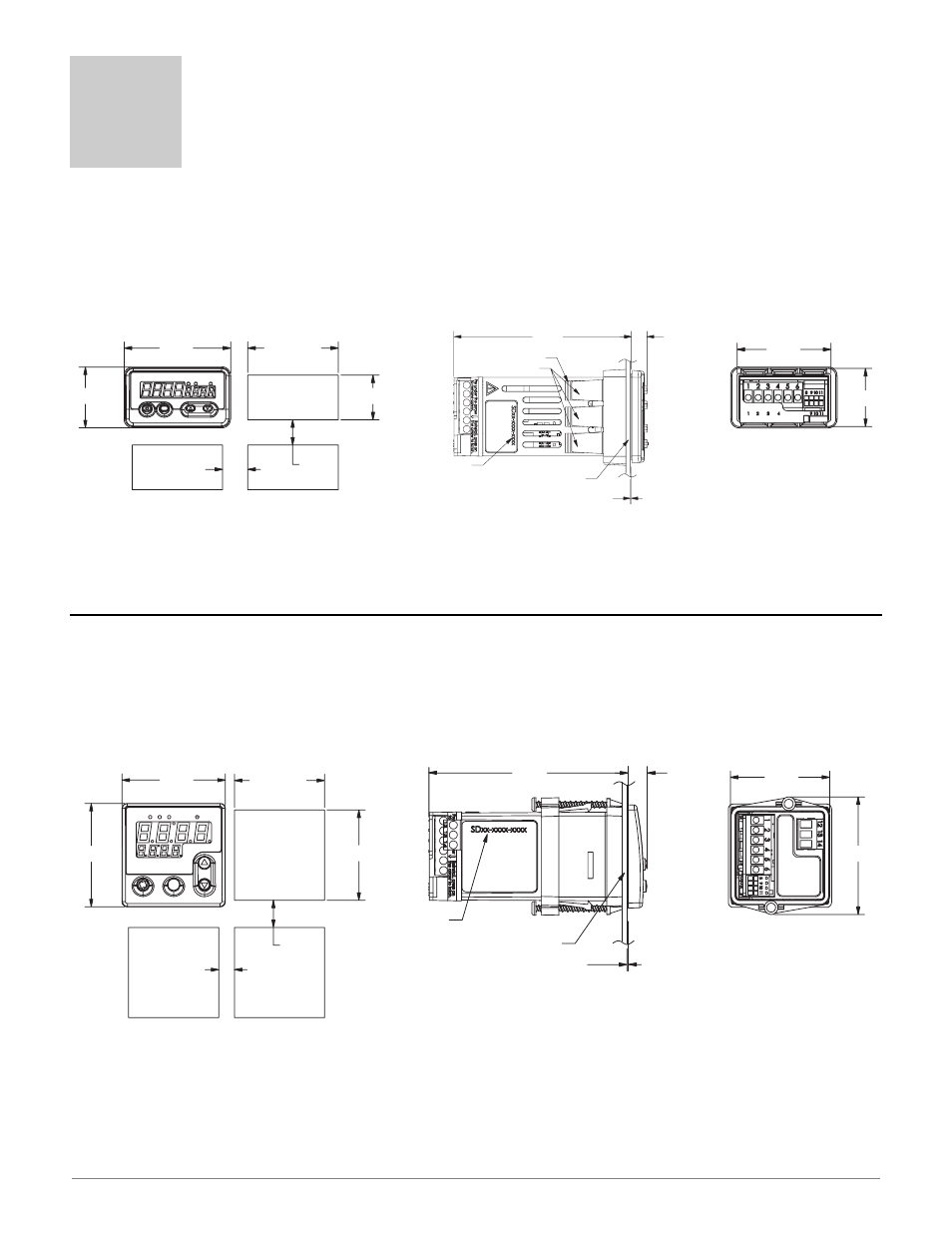
1/16 DIN Series SD Limit Dimensions
100.2 mm
(3.95 in)
9.3 mm
(0.37 in)
Model Number
Customer Front Panel
0.6 mm (0.025 in) maximum gap between
controller front and customer front panel
50.1 mm
(1.97 in)
59.2 mm
(2.33 in)
52.1 mm
(2.05 in)
45.0 to 45.5 mm
(1.77 to 1.79 in)
Panel Cutout
Panel Thickness
1.5 to 9.5 mm
(0.060 to 0.375 in)
45.0 to 45.5 mm
(1.77 to 1.79 in)
13.7 mm
(0.54 in)
minimum
7.9 mm
(0.31 in)
minimum
52.1 mm
(2.05 in)
RESET
RESET
Front
Side
Back
30.7 mm
(1.21 in)
53.6 mm
(2.11 in)
12.7 mm
(0.50 in)
minimum
45.0 to 45.6 mm
(1.77 to 1.79 in)
Panel Cutout
Panel Thickness
1.5 to 9.5 mm
(0.060 to 0.375 in)
22.2 to 22.5 mm
(0.87 to 0.89 in)
12.7 mm
(0.50 in)
minimum
RESET
RESET
100.9 mm
(3.98 in)
Ridges
Tabs with Teeth
Model Number
Customer Front Panel
0.48 mm (0.019 in) maximum gap between
controller front and customer front panel
8.6 mm
(0.34 in)
47.2 mm
(1.86 in)
29.3 mm
(1.15 in)
1/32 DIN Series SD Limit Dimensions
Front
Top
Back
Contact your local Greenlee supplier for the appropriate punch kit and
cutout tools required for rapid mounting.
Contact your local Greenlee supplier for the appropriate punch kit and
cutout tools required for rapid mounting.