Dip switches, Input 1 input 2 (remote set point), Figure 1.2 - input dip switches – Watlow Series 988LF User Manual
Page 8
1.2
WATLOW Series 988LF User’s Manual
Hardware Setup, Chapter 1
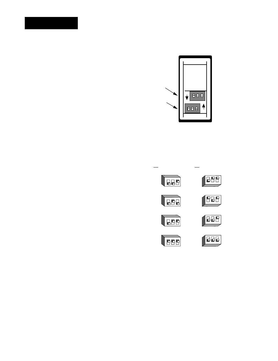
DIP Switches
Figure 1.2 -
Input DIP switches.
Input 1
Input 2
(Remote Set Point)
(98_L-2___-AA__)
(98_L-_2__-AA__)
RTD
thermocouple: R, S or B
thermocouple: J, K, T, N, E, C, D, Pt2
or 0-50mV (high impedance)
0-20 or 4-20mA; 0-5, 1-5 or 0-10V
O
N
↑
1
2
3
O
N
↑
1
2
3
O
N
↑
1
2
3
O
N
↑
1
2
3
O
N
↑
1
2
3
O
N
↑
1
2
3
O
N
↑
1
2
3
O
N
↑
1
2
3
Controller Chassis
Rear View
Input 1 DIP
Input 2 DIP
ON
ON
❶ Set the input DIP
switches to match the sen-
sors you are using in your
application. Only con-
trollers with model num-
ber 98_L-2___-AA__ or
98_L-_2__-AA__ have an
input DIP switch.
NOTE:
The Input 2 DIP
switch is mounted
upside down.
NOTE:
Only controllers
with the indicated
model numbers
have these DIP
switches.
See also other documents in the category Watlow Sensors:
- 12LS Controller (111 pages)
- 8LS Controller (140 pages)
- 8PID Controller (55 pages)
- Addendum to EZwarePlus (50 pages)
- ANASCAN (62 pages)
- ANASOFT (95 pages)
- ANAWIN 2 (154 pages)
- ANAWIN 3 (23 pages)
- Calibrating Watlow Series 988 Family Process Controls (19 pages)
- CAS (98 pages)
- CAS200 (124 pages)
- CLS (180 pages)
- CLS200 (251 pages)
- CLS200, MLS300 and CAS200 (92 pages)
- Control Console (12 pages)
- CPC400 (230 pages)
- DIN-A-MITE Style A (9 pages)
- DIN-A-MITE Style B (14 pages)
- DIN-A-MITE Style C (22 pages)
- DIN-A-MITE Style D (9 pages)
- DIN-Mount Adapter Instruction Sheet, Rev A (1 page)
- Dual DAC (4 pages)
- EM Gateway (28 pages)
- E-Safe Hybrid Relay Rev B (4 pages)
- E-SAFE II Hybrid Power Switch (4 pages)
- EZwarePlus Programming (264 pages)
- EZ-ZONE PM (111 pages)
- EZ-ZONE PM PID (125 pages)
- EZ-ZONE PM Express Limit (34 pages)
- EZ-ZONE PM Express (35 pages)
- EZ-ZONE PM Integrated Controller (181 pages)
- EZ-ZONE RM Limit Module Rev C (127 pages)
- EZ-ZONE RMA Modul (79 pages)
- EZ-ZONE RMC (236 pages)
- EZ-ZONE RME (124 pages)
- EZ-ZONE RMH (161 pages)
- EZ-ZONE RUI/Gateway (62 pages)
- EZ-ZONE RM-Scanner-Modul (140 pages)
- EZ-ZONE ST (97 pages)
- F4 External Event Board - Rev.B (2 pages)
- HG Series Mercury Displacement Relay (6 pages)
- LogicPro (296 pages)
- Mercury Relay or MDR Retrofit (13 pages)
- MICRODIN (24 pages)
- MICRODIN (106 pages)