Wiring the series 988lf, Input-to-output isolation, Power wiring – Watlow Series 988LF User Manual
Page 13: Sensor installation guidelines, Wiring
WATLOW Series 988LF User’s Manual
2.3
Installation and Wiring, Chapter 2
Wiring
Wiring the Series 988LF
Wiring options depend on the model number and DIP switch settings.
Check the terminal designation stickers on either side of the controller
and compare your model number to those shown here and with the model
number breakdown on the inside back cover of this manual.
Input-to-output Isolation
The Series 988LF uses optical isolation between the analog inputs and the
controller outputs. This isolation provides a 500V~ (ac) barrier to prevent
ground loops when using grounded sensors and/or peripheral equipment.
Here is a breakdown of the isolation barriers:
• Analog inputs 1 and 2 are grouped together.
• Outputs 1 and 2 are grouped together.
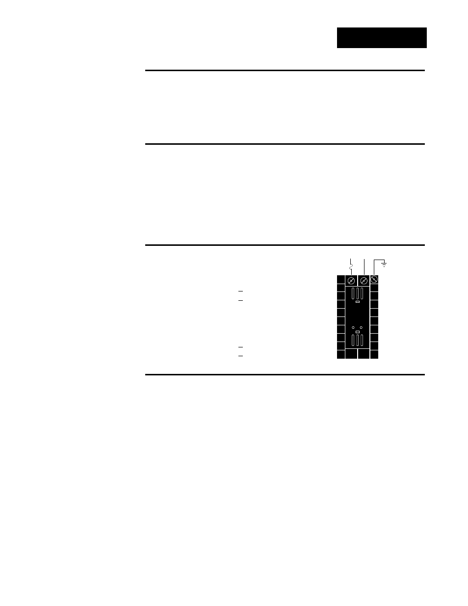
Power Wiring
100 to 240 V~ (ac), nominal (85 to 264 actual)
Vertical Package
98 8 L - _ _ _ _ - A A _ _
Horizontal Package
98 9 L - _ _ _ _ - A A _ _
24 to 28 V
‡
‡
(ac/dc), nominal (20 to 30 actual)
Vertical Package
98 6 L - _ _ _ _ - A A _ _
Horizontal Package
98 7 L - _ _ _ _ - A A _ _
Sensor Installation Guidelines
Thermocouple input: Extension wire for thermocouples must be of the
same alloy as the thermocouple itself to limit errors.
Using grounded thermocouples for both input 1 and remote set point
option may create ground loop problems. To correct this problem, replace
at least one of the grounded thermocouples with an ungrounded thermo-
couple. If the application requires grounded thermocouples, use an isolat-
ed transmitter, such as a Watlow Gordon 5702 isolated transmitter.
RTD input: Each 1
Ω
of lead wire resistance can cause a +2°F error when
using a two-wire RTD. A three-wire RTD sensor overcomes this problem.
All three wires must have the same electrical resistance (i.e., same gauge,
same length, multi-stranded or solid, same metal).
Process input: Maintain isolation between input 1 and input 2 to prevent
a ground loop. A ground loop may cause incorrect readings, dashes
across the upper display or the display of error codes.
fuse
22
21
earth ground
11
L2
L1
+
-
∫
WARNING:
To avoid potential
electric shock, use
National Electric
Code (NEC) safety
practices when
wiring and connect-
ing this unit to a
power source and
to electrical sensors
or peripheral
devices. Failure to
do so could result
in injury or death.
Figure 2.3 -
Power wiring.
ç
CAUTION:
The Series 988LF
will not function
with two grounded
thermocouple
inputs. Avoid using
a grounded thermo-
couple for both
input 1 and input 2.
Failure to follow this
guideline could
result in damage to
equipment.