Input 1 wiring, Thermocouple or 0-50mv (high impedance) – Watlow Series 988LF User Manual
Page 17
WATLOW Series 988LF User’s Manual
2.7
Installation and Wiring, Chapter 2
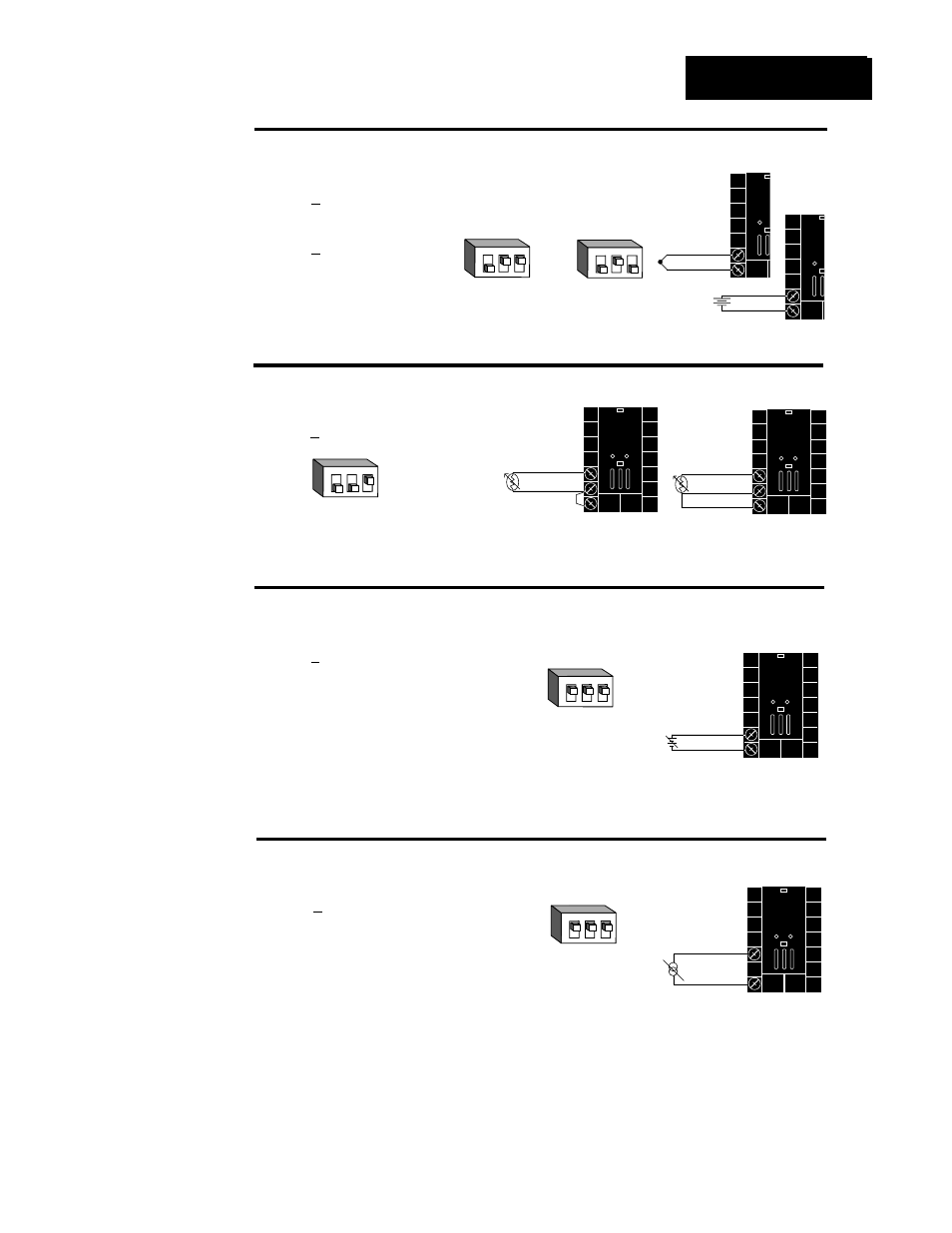
Figure
2.7
c —
0-5V
О
О
, 1-5V
О
О
or 0-10V
О
О
(dc) Process
Universal signal conditioner
98 _ L - 2 _ _ _ - A A _ _
Input impedance: 10K
Ω
Figure
2.7
a —
Thermocouple or 0-50mV (high impedance)
Thermocouple only
98 _ L - 1 _ _ _ - A A _ _ (no DIP switches)
Universal signal conditioner
98 _ L - 2 _ _ _ - A A _ _
Input impedance: 20M
Ω
Figure
2.7
b —
RTD (2 or 3 Wire) 100
Ω
Universal signal conditioner
98 _ L - 2 _ _ _ - A A _ _
9
10
+
-
0-50mV
9
10
8
S2
S1
S3
10
9
-
+
Figure
2.7
d —
0-20mA or 4-20mA Process
Universal signal conditioner
98 _ L - 2 _ _ _ - A A _ _
Input impedance: 7
Ω
10
8
-
+
9
10
8
S2
S1
DIP Switch
Setting
R, S, B
DIP Settings
J, K, T, N, C, E, D, Pt2,
0-50mV DIP Settings
DIP Switch
Setting
DIP Switch
Setting
NOTE:
Successful installa-
tion requires five
steps:
• Model number and
software choice
(Appendix);
• DIP switch set-
tings (Chapter 1);
• Sensor match
(Chapter 2 and
Appendix);
• Sensor installation
(Chapter 2); and
• Wiring (Chapter 2).
O
N
↑
1
2
3
O
N
↑
1
2
3
O
N
↑
1
2
3
9
10
+
-
Jumper
#9 to #10
for 2 wire
RTD
Input 1 Wiring
O
N
↑
1
2
3
O
N
↑
1
2
3
ç
CAUTION:
An external resistor
is required for
0-20mA and 4-20mA
process wiring to
prevent a high in-
rush current which
could burn out the
controller’s 7-ohm
resistor. See page
2.4 for recommen-
dations.