Output 2 wiring, Ac outputs, Switched dc, open collector – Watlow Series 988LF User Manual
Page 20: Figure 2.10a, 98 _ l - _ _ _ b - a a, 98 _ l - _ _ _ d - a a, 98 _ l - _ _ _ e - a a, 98 _ l - _ _ _ k - a a, Figure 2.10b, 98 _ l - _ _ _ c - a a
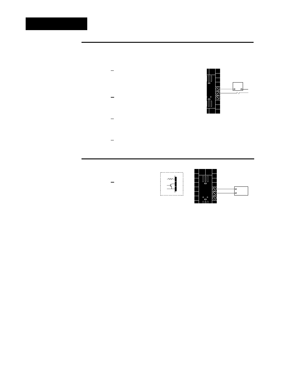
Figure 2.10a —
AC Outputs
Solid-state Relay with Contact Suppression
98 _ L - _ _ _ B - A A _ _
0.5 amps, minimum off-state impedance: 20K
Ω
Electromechanical Relay with Contact Suppression
(NO and COM contacts only)
98 _ L - _ _ _ D - A A _ _
Form C, 5 amps, minimum off-state impedance: 20K
Ω
Electromechanical Relay without Contact Suppression
98 _ L - _ _ _ E - A A _ _
Form C, 5 amps off-state impedance: 31M
Ω
Solid-state Relay without Contact Suppression
98 _ L - _ _ _ K - A A _ _
0.5 amps, off-state impedance: 31M
Ω
2.10
WATLOW Series 988LF User’s Manual
Installation and Wiring, Chapter 2
Figure 2.10b —
Switched DC, Open Collector
98 _ L - _ _ _ C - A A _ _
Minimum load resistance: 500
Ω
NOTE:
Successful installa-
tion requires five
steps:
• Model number and
software choice
(Appendix);
• DIP switch set-
tings (Chapter 1);
• Sensor match
(Chapter 2 and
Appendix);
• Sensor installation
(Chapter 2); and
• Wiring (Chapter 2).
15
External
Load
+
16
17
-
COM
External
Load
COM
L1
L2
Fuse
NO
15
16
NC
17
(#17 for D & E outputs only)
+ VDC
Internal Circuitry
15
16
17
790
Ω
19 to 32V
Î
(VDC)
Output 2 Wiring