Changing the position of a switch, Changing the position of a dip switch, Dip switch location and orientation – Watlow Series 920 Microprocessor-Based Ramping Control User Manual
Page 9: Figure 3, 9 dip switch selection table 1
DIP
Function
Normal
Table 1 -
SW#
Operating
DIP Switch
ON
OFF
Position
Selection.
1
Cold Start
Warm Start OFF
2
Not Used
Not Used
OFF
3
Tenths of units displayed
No decimal displayed
Choose
4
0-5VDC/0-20mA input
l-5VDC/4-20mA input
Choose
5
Primary output is 4-20mA
Primary output is not 4-20 Model # Dep,
6
LEDs are load indicators
LEDs are ° F or ° C
Choose
7
Selected SPCLFUNC promts All SPCLFUNC prompts
Choose
8
Factory Test/Calibrate
Normal Operation
OFF
DIP switch #1 determines a warm or cold start. A
“warm”
start saves all pro-
grammed information in the 920s memory back-up protection. A “cold” start is a
“clean” startup condition; all user-programmed information is lost. The Series
920 leaves the factory programmed for a warm start.
DIP switch #2 is not used.
DIP switch #3 determines if the decimal point is displayed in tenths of units for
process inputs.
DIP switch #4 is for 0-5VDC/0-20mA input or l-5VDC/4-20mA input selection.
DIP switch #5 is for units with 4-20mA output. If your unit has 4-20mA output,
set switch # 5 ON for the Primary output.
DIP switch #6 determines the function of the front panel LEDs to the right of the
actual display. When ON, these LEDs can be used as a diagnostic tool for tuning
or system troubleshooting, see Page 12 and 33.
DIP switch #7 is OFF, all SPCLFUNC prompts are displayed, when ON, only
factory selected prompts appear. See Page 42. DIP switch #8 is a factory test/
calibrate switch.
Changing the Position of a Switch
Whenever you change the position of a DIP switch, follow this procedure:
1.
2.
3.
4.
5.
Remove power from the 920. Turn the front panel screw 90°counterclockwise.
Grip the front panel bezel and pull it straight out from the control case.
The control chassis will come out of the case as you pull the bezel.
Set the DIP switch to the position you want.
Return the control chassis to the case. Be sure you have it oriented cor-
rectly. It will not fit in upside down, but check just the same. Press
firmly, but gently, to seat the chassis.
Secure the front panel screw and re-apply power to the 920.
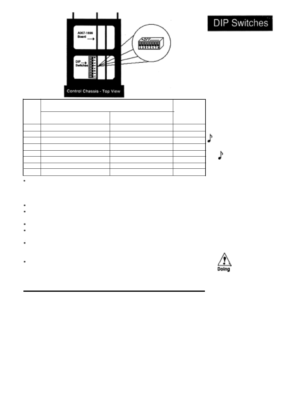
Figure 3 -
DIP Switch Location
and Orientation.
NOTE:
For units with
process input only.
If your unit does not
have process input,
DIP Switch #3
should be in the OFF
position.
WARNING:
a cold start
will cause all setup
parameters and files
to be lost. DO NOT
put DIP switch #1 in
the ON position
unless all user-
programmed
information is to be
cleared.
Starting
Out,
Chapter
1
WATLOW Series 920
User’s Manual
9