How to open the 920, How to set the dip switches, How to open the 920 how to set the dip switches – Watlow Series 920 Microprocessor-Based Ramping Control User Manual
Page 8: How to open the series 920, Figure 2
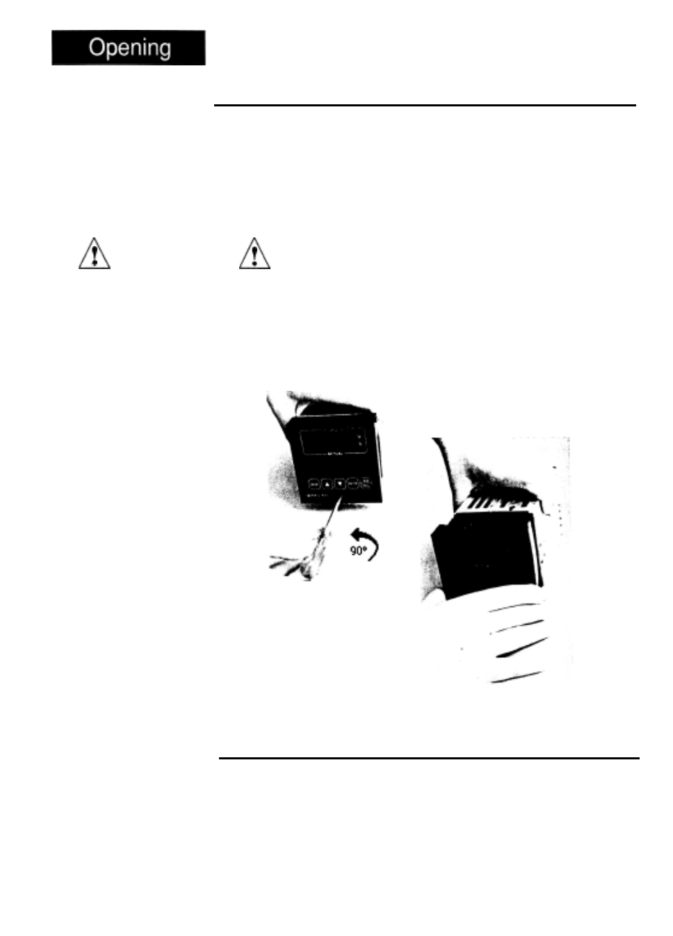
How to Open the 920
CAUTION:
The front panel
screw turns 90°
only. Do not apply
excessive force or
turn the screw more
than 90°.
Figure 2 -
How to Open the
Series 920.
Before going further, open the Series 920 and pull the control chassis from its
case. Here’s how:
The control chassis fastens to the case with a single screw located on the
lower front panel. See Figure
2.
Turn the screw counterclockwise to loosen it.
Three or four strip connector
plugs, in the rear of
the control chassis, feed
power and signals through the back of the casing to the triple terminal strip.
These plugs will let go as you pull.
l
When removing the Series 920 control from its case, pull firmly but gently.
When returning the control to the case, be sure you have the top up to match
the plugs with the case. The 920 will not fit in to the case upside down. Al-
ways check to see that it is oriented correctly. Press the unit in firmly, then turn
the front panel screw clockwise to secure it.
How to Set the DIP Switches
The Watlow Series 920 has a Dual In-line Package (DIP) switch inside the
control on circuit board AOO7-1699. The locations of the board and switch
appear in Figure 3. The switches are clearly numbered from left to right. You
will use DIP switches #1 and 3
-
8; #2 is not used. Table 1 on the next page
shows the DIP switch selections.
8
WATLOW Series 920 User’s Manual Starting Out Chapter 1