How to wire the series 920, Figure 13 figure 14, Panel cutout – Watlow Series 920 Microprocessor-Based Ramping Control User Manual
Page 25
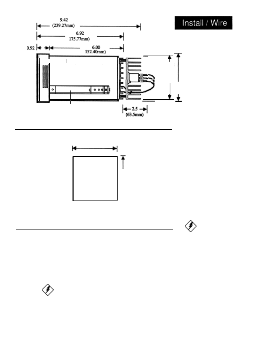
(23.37mm)
& - B e z e l
Mounting
Bracket
3.56 ± 0.015
(90.42mm
±0.381
Your Panel
Thickness
0.06 to 0.25
(1.524 to 6.35mm)
3.622 to 3.653
(92.00 to 92.79mm)
Panel
cutout
3.625 x 3.625
(92.08 x 92.08mm)
Nominal
How to Wire the Series 920
3.622 to 3.653
(92.00 to 92.79mm)
I
This section has all the information you need to complete a good wiring job on
the Series 920 and your system. Please read the Safety Information in the
narrow column on the outside of each page. You will find internal circuits on
the left in the following diagrams, and external circuits on the right. In addition,
output options are listed by model number. Refer to the unit sticker on your
control to be sure that you are wiring from the corresponding diagram. We
suggest that you read through the entire section before beginning your hookup.
Then proceed, starting with the sensor inputs, auxiliary outputs, then control
outputs, data communications, and finally, power wiring.
It is very important to enter a system set point in the Series 920 before
applying
power to the load circuitry.
l
In all wiring diagrams, internal circuits are on the left and external
circuits
are on the right.
3.81
(96.77mm)
Figure 13 -
Series 920
Dimensions.
(side view)
Figure 14 -
Series 920
Panel Cutout
Dimensions.
WARNING:
To avoid electric
shock, make all
connections on the
back of the control
before connecting
power to the control.
Also, disconnect
p o w e r b e f o r e
opening the Series
920.
Do not apply
load power to the
output circuits until
you have entered a
system set point
How to Install and Wire, Chapter 4 WATLOW Series 920 User's Manual 25