Keyboard area, Where to go from here, Keyboard front panel information – Watlow Series 920 Microprocessor-Based Ramping Control User Manual
Page 13: Figure 7
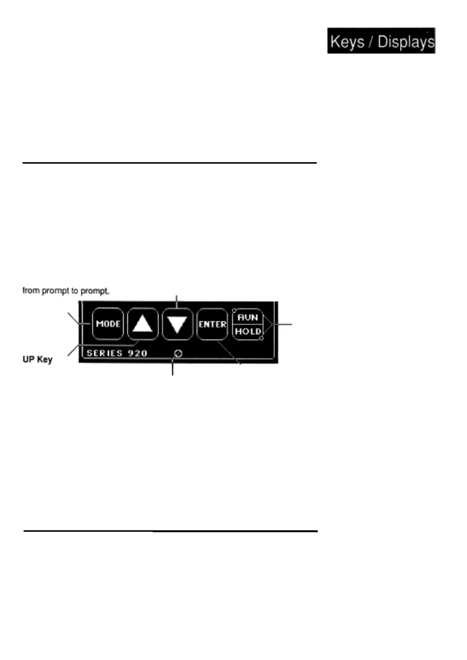
Keyboard Area
Figure 7 -
DOWN Key
Acts opposite the UP
key. Decreases the
value in the alpha-
numeric display. A light
touch decreases the
MODE Key
This key steps the
Series 920 in sequence
value by one digit. Hold
the key down to de-
crease the displayed
value at a rapid rate.
in the alphanumeric
Increases the value
display. A light
touch increases the
value by one digit.
Hold the key down
to increase the
displayed value at
a rapid rate.
90° Front Panel Screw
Secures the control
chassis in its case with
a 1/4 turn clockwise or
releases the chassis
with a 1/4 turn counter-
clockwise.
ENTER Key
Enters selected
(flashing) data into
the microprocessor
memory, or will mask
an error code or
latched alarm for 1
minute.
Where To Go From Here
Keyboard Front
Panel Information.
RUN/HOLD Key
Executes or holds a
program from the
SYSTEM menu.
Run/Hold LEDs
When the HOLD LED is
ON steady, the 920 is in
a HOLD condition.
When the HOLD LED
flashes, the unit is
holding for a WAITFOR
condition, or a guaran-
teed soak condition.
When the RUN LED is
ON the 920 is in the
RUN condition.
Now that you have a good idea where everything is on the faceplate of the
Series 920, continue to Chapter 3 for the Sample Program. If you skip the
sample program, do not forget to check the position of DIP switch #1 before
you begin programming your control after installation. With DIP switch #1
OFF, the 920 saves your program whenever power is removed (warm start).
With DIP switch #1 ON, the 920 will clear its memory of all programmed
information whenever power is removed, substituting default values (cold
start).
How to Use Keys and Displays, Chapter 2
WATLOW Series 920 User’s Manual
13