Process field calibration procedure, Figure 39, Equipment required – Watlow Series 920 Microprocessor-Based Ramping Control User Manual
Page 66: Set-up and calibration
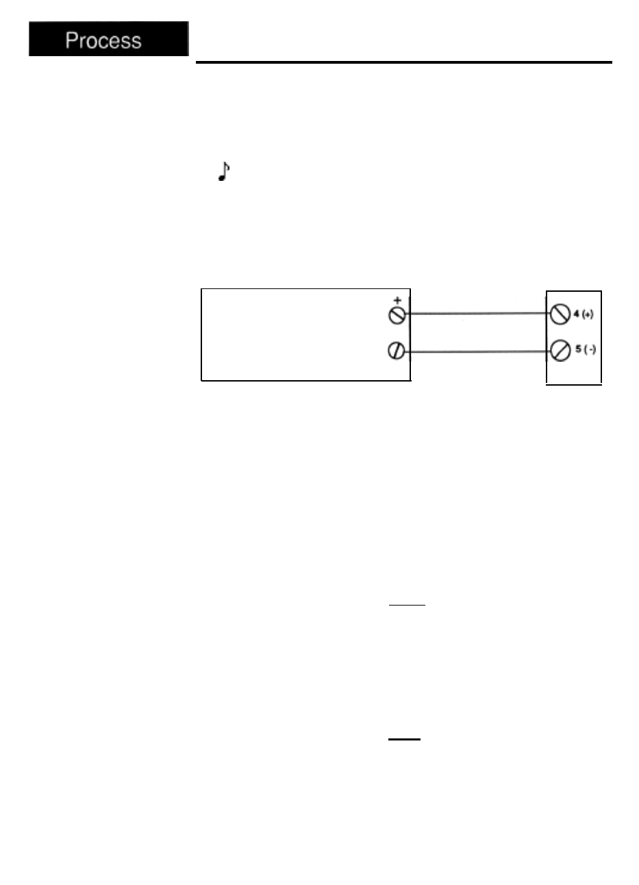
Process Field Calibration Procedure
Figure 39 -
Voltage/Current
Source to
Series 920
Connection
Diagram
Equipment Required
l
4-1/2 digit, digital voltmeter (DVM).
l
Precision voltage/current source.
Set-up and Calibration
NOTE:
Before calibration on an installed control, make sure all data and parame-
ters are documented.
1.
Connect the voltage/current source to #4 Positive and #5 Negative on the
Series 920 terminal strip. See the figure below.
Series 920
Terminal Strip
Voltage/Current
Source
2.
3.
4.
5.
6.
7.
8.
9.
,
.
Connect AC line voltage, L1 to #17, L2 to
#20,
ground to #21 on the Series
920 terminal strip.
Set DIP switch #8 ON. Apply power to the 920 and allow it to warm up for
15 minutes. The unit should be in the TEST mode.
Using the MODE key, advance until the IN X parameter appears on the
alphanumeric display. Using the UP/DOWN keys, advance to the correct
input type. Press the ENTER key.
Connect DVM common to TP84 and DVM positive to TP36 on the AOO7-
1703 circuit board. Located on the top side behind the center chassis
support. DVM should be set up for DC volts, and in a range capable of
displaying 32.00 ± 10mv.
Press the MODE key until HOF XX.XX appears on the alphanumeric dis-
play. (The decimal point will not appear on the display of your control.)
Use the UP/DOWN keys to adjust the alphanumeric display on the 920 to
match the reading on the DVM. Once the two readings match, press the
ENTER key.
Press the MODE key until MA2 XXXX appears. Input 0 volts for a 0-5 volt
input type, or 4mA for a 4-20mA input type. Press the ENTER key.
Allow
10 seconds for the unit to stabilize.
Press the MODE key until MAG XXXX appears. Inpuy 5 volts for a 0-5 volt
input type, or 20mA for a 4-20mA input type. Press the ENTER key. The
unit is now calibrated for process inputs. Allow 10 seconds to stabilize.
The process reading on the ACTUAL display should be sitting at the RAH
setting.
Remove power for the Series 920. Remove wires from #4 and #5. Set DIP
Switch #8 to the OFF position.
66
WATLOW Series 920 User’s Manual
Appendix