Installation information, Installation procedure, Series 920 faceplate dimensions – Watlow Series 920 Microprocessor-Based Ramping Control User Manual
Page 24: Figure 12
Installation Information
CAUTION:
The front panel
screw turns 90°
only. Do not apply
excessive force or
turn the screw more
than 90°.
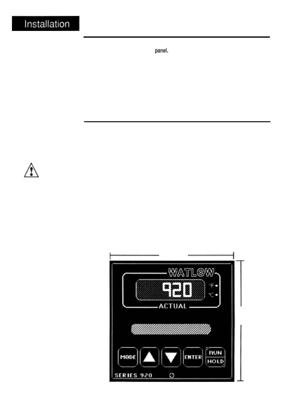
Figure 12 -
Series 920 Faceplate
Dimensions.
The Series 920 mounts in a panel cutout with two brackets. These brackets
hold the case against the front
The Series 920 behind-panel dimensions
are 3.56 in. (90.42mm) high by 3.56 in. (90.42mm) wide by 6.0 in. (152.4mm)
deep. If your unit has a triac output, add another 2.5 in (63.5mm) to the depth.
Figure 12 shows the dimensions of the front panel bezel. The 920 weighs 2.75
lbs. (1.25Kg).
For unit dimensional and mounting information, including the location of mount-
ing brackets and size of the front panel cutout, see Figures 13 and 14. Your
panel’s thickness can be from 0.06 (1.5mm) to 0.25 in. (6.3mm).
Installation Procedure
Follow this procedure to mount the Watlow Series 920 Temperature Control:
1.
2.
Make a panel cutout per the dimensions in Figure 14.
Remove the 920 from its case by turning the front panel screw 90° counter-
clockwise (CCW). Grip the bezel firmly and pull the control chassis out of
the case.
3.
4.
Place the case in the cutout you just made.
Attach the mounting brackets either to the top and bottom, or to both sides
of the unit.
5. Tighten the mounting brackets securely against your panel.
6.
Insert the control chassis into its case and press the bezel to seat it. Turn
the front panel screw 90° clockwise (CW) to lock the control in place. The
hardware installation is complete. Go on to the wiring section from here.
3.81 Sq.
(96.77mm)
3.81 Sq.
(96.77mm)
24
WATLOW Series 920 User’s Manual
How to Install and Wire, Chapter 4