Output #2, Output 2 wiring, Output 1,4-20ma, wiring diagram – Watlow Series 920 Microprocessor-Based Ramping Control User Manual
Page 30: No output 2, Output 2, s.s. relay, wiring diagram, Figure 22 figure 23 figure, Output, #l option f, terminals 22 - 24
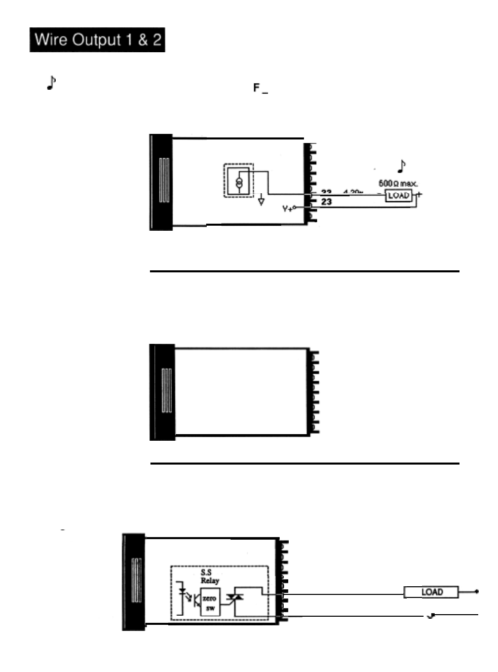
Output, #l Option F, Terminals 22 - 24
NOTE:
Current for the
4-20mA loop is
sourced internal to
the control.
Use ungrounded
sensors only.
Figure 22 -
output 1,4-20mA
Option "F",
Wiring Diagram.
Figure 23 -
No Output 2.
Model #920A-_
F _ _-_000
Output #1 to
Load from
4-20mA source
2 4
mA
Output # 2 Option A, Terminals 14 - 16
Model #92OA-
A_-_000
- -
14 Not Used
16 Not Used
Figure 24 -
output 2 S.S. Relay,
Option "B", Wiring
Diagram.
Output # 2 Option B, Terminals 14 - 16
Model #920A-
B_-_000
- -
Output
#2 to
Load from
S.S.
Relay, 0.5A
14 N.O. (MT2)
16 COM (MT1)
l
L2
L1
30
WATLOW Series 920 User’s Manual How to Install and Wire, Chapter 4
See also other documents in the category Watlow Sensors:
- 12LS Controller (111 pages)
- 8LS Controller (140 pages)
- 8PID Controller (55 pages)
- Addendum to EZwarePlus (50 pages)
- ANASCAN (62 pages)
- ANASOFT (95 pages)
- ANAWIN 2 (154 pages)
- ANAWIN 3 (23 pages)
- Calibrating Watlow Series 988 Family Process Controls (19 pages)
- CAS (98 pages)
- CAS200 (124 pages)
- CLS (180 pages)
- CLS200 (251 pages)
- CLS200, MLS300 and CAS200 (92 pages)
- Control Console (12 pages)
- CPC400 (230 pages)
- DIN-A-MITE Style A (9 pages)
- DIN-A-MITE Style B (14 pages)
- DIN-A-MITE Style C (22 pages)
- DIN-A-MITE Style D (9 pages)
- DIN-Mount Adapter Instruction Sheet, Rev A (1 page)
- Dual DAC (4 pages)
- EM Gateway (28 pages)
- E-Safe Hybrid Relay Rev B (4 pages)
- E-SAFE II Hybrid Power Switch (4 pages)
- EZwarePlus Programming (264 pages)
- EZ-ZONE PM (111 pages)
- EZ-ZONE PM PID (125 pages)
- EZ-ZONE PM Express Limit (34 pages)
- EZ-ZONE PM Express (35 pages)
- EZ-ZONE PM Integrated Controller (181 pages)
- EZ-ZONE RM Limit Module Rev C (127 pages)
- EZ-ZONE RMA Modul (79 pages)
- EZ-ZONE RMC (236 pages)
- EZ-ZONE RME (124 pages)
- EZ-ZONE RMH (161 pages)
- EZ-ZONE RUI/Gateway (62 pages)
- EZ-ZONE RM-Scanner-Modul (140 pages)
- EZ-ZONE ST (97 pages)
- F4 External Event Board - Rev.B (2 pages)
- HG Series Mercury Displacement Relay (6 pages)
- LogicPro (296 pages)
- Mercury Relay or MDR Retrofit (13 pages)
- MICRODIN (106 pages)
- MICRODIN (24 pages)