R, s, & b thermocouple field calibration procedure, R" reference compensator to 920 connection diagram, Figure 37 – Watlow Series 920 Microprocessor-Based Ramping Control User Manual
Page 63: Equipment required, Setup and calibration
R, S, & B Thermocouple Field Calibration Procedure
Equipment Required
l
Type “R” Reference Compensator with reference junction at
0°C/32° F OR
T/C calibrator.
l
Type “R” T/C Extension Wire.
l
Copper wire.
l
Precision Millivolt Source.
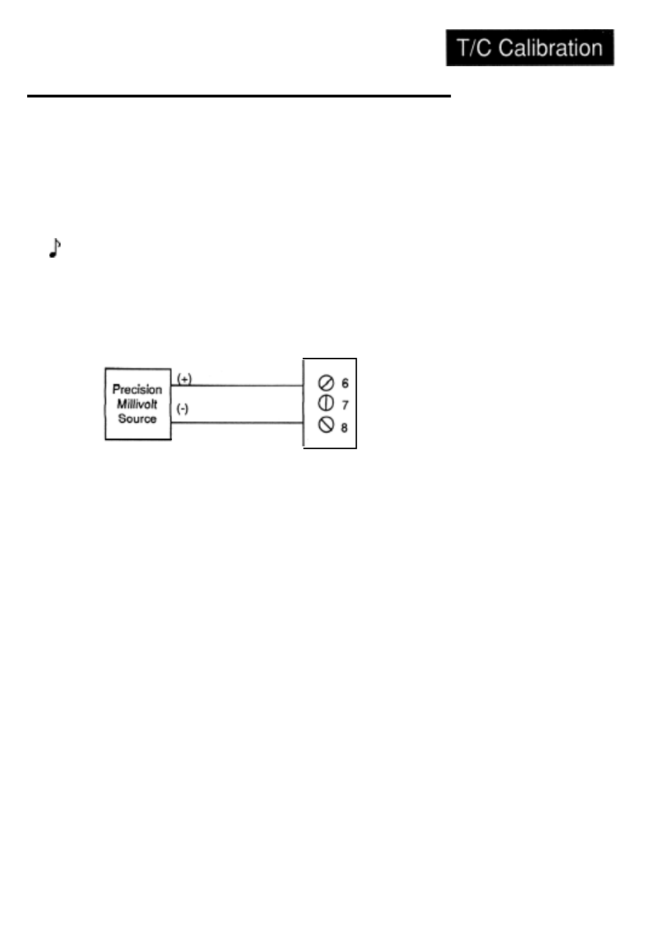
Setup and Calibration
1.
Connect the precision millivolt source to Terminals #6 and #8. See the figure
below.
Series 920
Terminal Strip
Figure 37 -
Type "R"
Reference
Compensator-to-
Series 920 Connec-
tion Diagram.
2.
3.
Connect AC line voltage, L1 to #17, L2 to #20, ground to #21.
Set DIP switch #8 to ON. Apply power to the unit and allow it to warm up
for 15 minutes. The unit should be in the TEST mode.
4.
Using the MODE key, advance until the IN X parameter appears on the
alphanumeric display. Using the UP/DOWN keys, advance to the “R”
thermocouple input type. Press the ENTER key.
5.
6.
Press the MODE key until the ATZ prompt will appear.
Set the precision millivolt source for an output of 0.000 millivolts, (32°F/0°C).
Allow 10 seconds for the control to stabilize, and press ENTER.
7.
8.
9.
10
11.
Press the MODE key, the ATG prompt appears in the alphanumeric display.
Set the precision millivolt source for an output of 16.035 millivolts, (2552°F/
1400°C). Allow 10 seconds for the control to stabilize and press ENTER.
Disconnect the millivolt source and connect the input side of the thermo-
couple reference compensator, or output of the T/C calibrator, to #6 Positive
and #8 Negative on the Series 920 terminal strip.
Connect the reference compensator to the 920. See Page 62, Figure 37.
Turn the compensator ON. Allow 10 seconds for the control to stabilize.
Press the MODE key, advance until the CJ prompt appears in the display,
press ENTER. The unit is now calibrated for R, S, and B T/C units.
Remove power from the Series 920. Remove the T/C wires from # 6 and #8.
Turn off the compensator. Set DIP switch #8 to the OFF position.
NOTE:
Before calibration on an installed control, make sure all data and
parameters are documented.
Appendix WATLOW Series 920 User's Manual 63