J, k, & t thermocouple field calibration procedure, Calibration, Figure 36 – Watlow Series 920 Microprocessor-Based Ramping Control User Manual
Page 62: Equipment required, Setup and calibration, Copper wires, T/c wires
J, K, & T Thermocouple Field Calibration Procedure
Equipment Required
l
T/C calibrator set at 0°C/32°F OR
Type “J”, “K”, or “T” Reference Compensator with reference junction at
0°C/32°F.
l
Type “J”, “K”, or “T” T/C extension wire.
l
4-1/2 digit Digital Voltmeter (DVM).
Setup and Calibration
NOTE:
Before calibration on an installed control, make sure all data and
parameters are documented.
1.
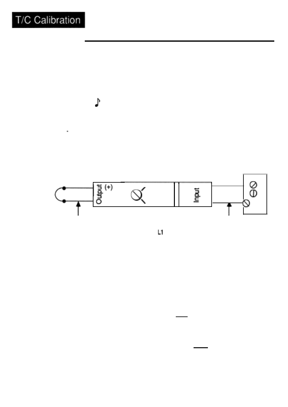
Connect the input side of the thermocouple reference compensator, or output
of the T/C calibrator to #6 Positive and #8 Negative on the Series 920 terminal
strip. Short the output side of the compensator and turn on the compensator.
Figure 36 -
Type J, K, or T
Reference Compen-
sator-to-Series 920
Connection
See Figure 36.
Omega Model
MCJ-J
Series 920
Terminal
Strip
I
I
Diagram.
(-)
Copper Wires
Open
-
Test
On
( )
+
#6
(-)
#8
T/C Wires
2.
3.
4.
5.
6.
7.
8.
Connect AC line voltage, to #17, L2 to #20, ground
to
#21.
Set DIP switch #8 to ON. Apply power to the unit and
allow
it to warm up
for 15 minutes. The unit should be in the TEST mode.
Using the MODE key, advance until the IN X parameter appears on the
alphanumeric display. Using the UP/DOWN keys, advance to the thermo-
couple input type. Press the ENTER key.
Connect DVM common to TP84 and DVM positive to TP36 on the AOO7-
1703 circuit board, (right most board) located on the top side behind the
center chassis support. DVM should be set up for DC volts, and in a range
capable of displaying 32.00 & 1 0mV.
Press the MODE key until HOF XX.XX appears on the alphanumeric display.
(The decimal will not appear on the display of your control.) Use the UP/
DOWN keys to adjust the alphanumeric display to match the reading on the
DVM. Once the two readings match, press ENTER.
Press the MODE key until parameter CJO XXXX appears. Press ENTER. The
.
unit is now calibrated for Type J, K, and T themocouple inputs. Allow 10
seconds for the unit to stabilize. The process reading on the ACTUAL display
should be 32°F (0°C).
Remove power from the Series 920. Remove thermocouple wires from #6
and #8. Turn off the compensator. Set DIP Switch #8 to the OFF position.
62
WATLOW Series 920 User’s Manual Appendix