Rtd field calibration procedure, Figure 38, Equipment required – Watlow Series 920 Microprocessor-Based Ramping Control User Manual
Page 64: Setup and calibration
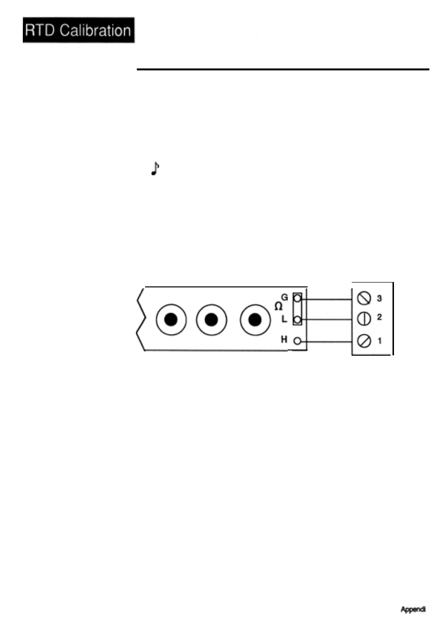
RTD Field Calibration Procedure
Figure 38 -
Decade
Resistance
Box-to-Series 920
Connection Diagram
Equipment Required
l
100 ohm precision decade resistance box with 0.00 ohms resolution.
l
4-1/2 digit, digital voltmeter (DVM).
Setup and Calibration
NOTE:
Before calibration on an installed control, make sure all data and parame-
ters are documented.
1.
Connect the precision decade box to
#1 ,
#2, and #3 of the Series 920
terminal strip as shown in the figure below.
Series
920
Terminal Strip
General Radio Model #1433-T
2.
Connect AC line voltage, L1 to #17, L2 to #20, ground to #21.
3.
Set DIP switch #8 ON. Apply power to the Series 920 and allow it to warm
up for 15 minutes. The unit should be in the TEST mode.
4.
Using the MODE key, advance until the IN X parameter appears in the
alphanumeric display. Using the UP/DOWN keys, advance to your correct
RTD input type. Press the ENTER key.
5.
Connect DVM common to TP84 and DVM positive to TP36 on the AOO7-
1703 circuit board. Located on the top side behind the center chassis
support. DVM should be set up for DC volts, and in a range capable of
displaying 32.00 millivolts ± 1 0mV.
64
WATLOW Series 920 User’s Manual