2 com port pin 9 setting jumpers, Figure 4-9: clear cmos jumper, Table 4-2: clear cmos jumper settings – IEI Integration IMB-Q354 v1.10 User Manual
Page 70
IMB-Q354 microATX Motherboard
Page 70
Load Failsafe Defaults.
After having done one of the above, save the changes and exit the CMOS Setup menu.
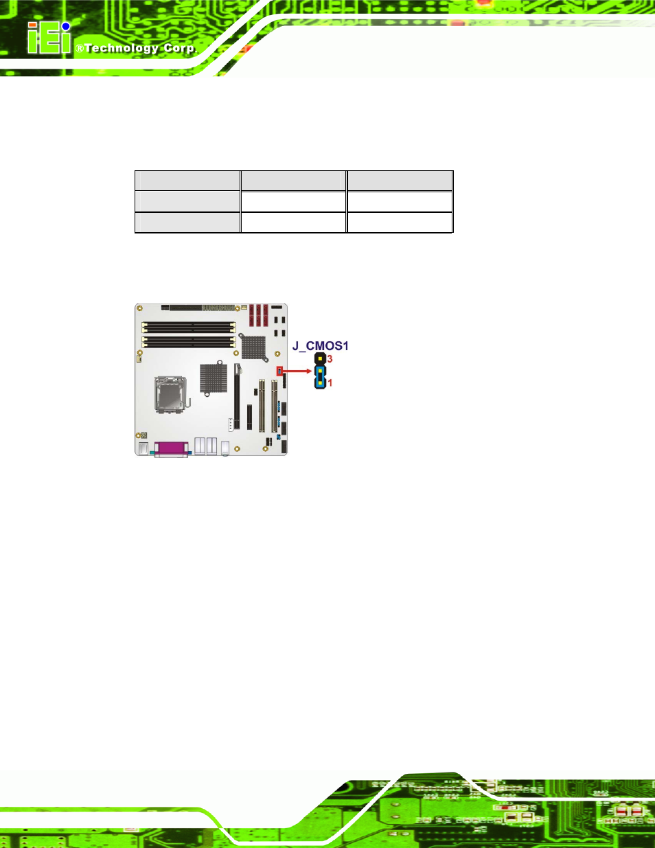
The clear CMOS jumper settings are shown in Table 4-2.
Clear CMOS
Description
Short 1 - 2
Keep CMOS Setup
Default
Short 2 - 3
Clear CMOS Setup
Table 4-2: Clear CMOS Jumper Settings
The location of the clear CMOS jumper is shown in Figure 4-9 below.
Figure 4-9: Clear CMOS Jumper
4.5.2 COM Port Pin 9 Setting Jumpers
Jumper Label:
J_COM_F2, J_COM_F3 and J_COM_F4
Jumper Type:
3-pin header
Jumper Settings:
Jumper Location:
The COM Port Pin 9 Setting jumpers configure pin 9 on COM 2/COM 3/COM 4 as either a
+5V, +12V power source (see Section 4.5.3 to setup) or as a ring-in (RI) line. The COM
Port Pin 9 Setting jumpers selection options are shown in Table 4-3.
- SPCIE-5100DX (180 pages)
- SPCIE-C2060 v1.01 (200 pages)
- SPCIE-C2060 v2.12 (212 pages)
- SPCIE-C2160 (204 pages)
- SPCIE-C2260-i2 (217 pages)
- ROCKY-3786 v4.0 (175 pages)
- ROCKY-3786 v4.10 (147 pages)
- PCIE-Q350 v1.00 (272 pages)
- PCIE-Q350 v1.12 (250 pages)
- PCIE-Q350 v1.20 (250 pages)
- PCIE-Q350 v1.30 (213 pages)
- PCIE-Q57A (159 pages)
- PCIE-G41A2 (151 pages)
- PCIE-Q670 v1.03 (206 pages)
- PCIE-Q670 v2.00 (205 pages)
- PCIE-H610 (181 pages)
- PCIE-Q870-i2 (217 pages)
- IOWA-LX-600 (159 pages)
- PCISA-945GSE v1.01 (207 pages)
- PCISA-945GSE v1.10 (190 pages)
- PCISA-9652 v1.00 (232 pages)
- PCISA-9652 v1.01 (232 pages)
- PCISA-PV-D4251_N4551_D5251 (145 pages)
- PICOe-945GSE (197 pages)
- PICOe-GM45A (198 pages)
- PICOe-PV-D4251_N4551_D5251 v1.00 (154 pages)
- PICOe-PV-D4251_N4551_D5251 v1.10 (154 pages)
- PICOe-PV-D4251_N4551_D5251 v1.11 (155 pages)
- PICOe-B650 (156 pages)
- PICOe-HM650 (174 pages)
- HYPER-KBN (139 pages)
- SPXE-14S (3 pages)
- SPXE-9S v1.00 (5 pages)
- SPXE-9S v1.1 (6 pages)
- SPE-9S v1.00 (4 pages)
- SPE-9S v1.1 (5 pages)
- SPE-6S (3 pages)
- SPE-4S (4 pages)
- PE-6SD3 (4 pages)
- PE-6SD2 v4.0 (4 pages)
- PE-6SD2 v2.10 (3 pages)
- PE-6SD (3 pages)
- PE-6S3 v1.0 (2 pages)
- PE-6S3 v4.0 (4 pages)
- PE-6S2 (4 pages)