1 peripheral interface connectors, 1 pcie-q350 layout, 2 peripheral interface connectors – IEI Integration PCIE-Q350 v1.30 User Manual
Page 65: Eripheral, Nterface, Onnectors, Figure 4-1: connector and jumper locations
PCIE-Q350 PICMG 1.3 CPU Card
Page 45
4.1 Peripheral Interface Connectors
Section 4.1.2 shows peripheral interface connector locations. Section 4.1.2 lists all the
peripheral interface connectors seen in Section 4.1.2.
4.1.1 PCIE-Q350 Layout
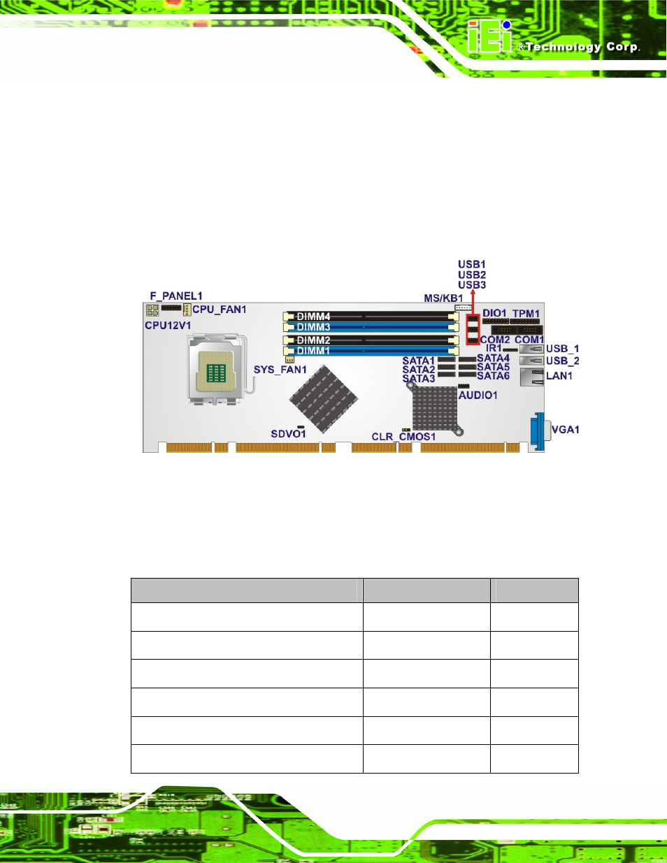
Figure 4-1 shows the on-board peripheral connectors, rear panel peripheral connectors
and on-board jumpers.
Figure 4-1: Connector and Jumper Locations
4.1.2 Peripheral Interface Connectors
Table 4-1 shows a list of the peripheral interface connectors on the PCIE-Q350. Detailed
descriptions of these connectors can be found below.
Connector
Type
Label
ATX power connector
4-pin ATX connector
CPU12V1
Audio connector
10-pin header
AUDIO1
Cooling fan connector, CPU
4-pin wafer
CPU_FAN1
Cooling fan connector, System 3-pin
wafer
SYS_FAN1
Digital input/output connector
18-pin header
DIO1
Front panel connector
14-pin header
F_PANEL1