4 sata drive connection, Figure 5-13: sata drive cable connection – IEI Integration PCIE-Q350 v1.30 User Manual
Page 104
PCIE-Q350 PICMG 1.3 CPU Card
Page 84
Step 3:
Secure the bracket. The dual RS-232 connector has two D-sub 9 male
connectors secured on a bracket. To secure the bracket to the chassis please
refer to the reference material that came with the chassis
Step 0:
5.7.4 SATA Drive Connection
To connect the SATA drives to the connectors, please follow the steps below.
Step 1:
Locate the connectors. The locations of the SATA drive connectors are shown
in Chapter 3.
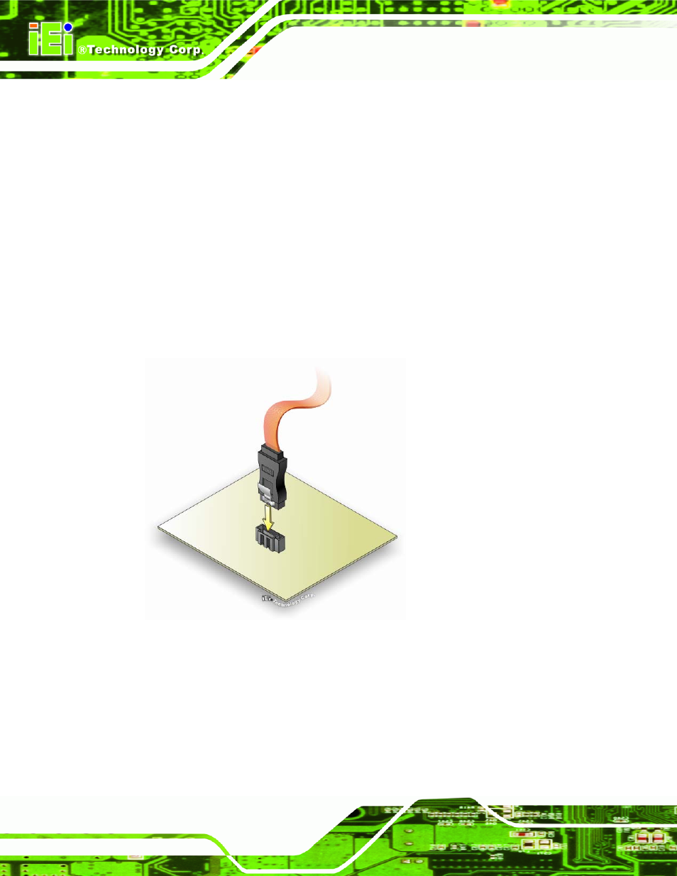
Step 2:
Insert the cable connector. Insert the cable connector into the on-board SATA
drive connector until it clips into place. See Figure 5-13.
Figure 5-13: SATA Drive Cable Connection
Step 3:
Connect the cable to the SATA disk. Connect the connector on the other end
of the cable to the connector at the back of the SATA drive. See Figure 5-14.
Step 4:
Connect the SATA power cable. Connect the SATA power connector to the
back of the SATA drive. See Figure 5-14.