Warner Electric SFPBC-500, SFPBC-650 User Manual
Page 6
6
Warner Electric • 800-825-9050
P-202-01 • 819-0482
from burrs and chips before assembling.
1.
Place the bushing into the hub and insert the
key. The key is a side-to-side fit and should
not contact the top of the keyway.
2.
Insert the locking setscrews loosely into the
bushing and slide the assembly onto the
shaft.
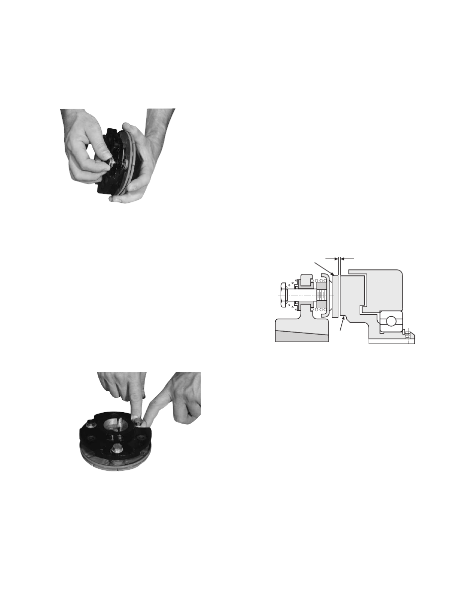
3.
If the field-and-rotor assembly has been
secured to the shaft first, then adjust the
armature’s position to allow approxi-
mately 1/32-inch between the two fac es.
Once this 1/32-inch gap has been set, it will
be au to mat i cal ly maintained throughout the
life of the unit. (Figure 11)
4.
Secure the armature’s position on the shaft by
al ter nate ly tightening each setscrew. During
the tight en ing process the bushing should
be tapped lightly to make sure it seats-in
properly.
Armature
1/32 inch Gap
Rotor
Figure 11
290 Loctite Sealant on the drive pin threads.
(Figure 9)
Step 5
Tighten the drive pins until the shoulders of
the pins are against the face of the armature
bosses. Since the threads are a class No. 3
fit, the pins may seem to bind.
Note:
Alternately tighten each drive pin a
few turns at a time.
Step 6
Compress the retainers against the armature
hub and check to see that the armature hub
is held tightly to the armature bosses. Note:
This position must not be dis turbed during
completion of assembly. (Figure 10)
E. Mounting the Armature Assembly
The armature assembly is mounted on the shaft with a
taperlock bushing. All parts must be clean and free
Figure 9
Figure 10