Installation instructions, Description, Components – Warner Electric SFPBC-500, SFPBC-650 User Manual
Page 19
19
Warner Electric • 800-825-9050
P-202-01 • 819-0482
Installation Instructions
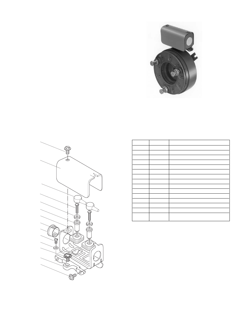
Conduit Box Kit No. 5200-101-010
Description
This Warner Electric conduit box is designed to
provide a proper means for field wiring ter mi na tions.
It conforms to the requirements of Un der writ ers
Laboratories. Kit No. 5200-101-010, plus magnet
terminal accessory kit, con tains all components
needed to assemble a conduit box for the above
mentioned units. Please follow these in struc tions
carefully when installing this conduit box. Fail ure to
comply with these instructions could result in un safe
electrical
connections.
4
10
8
11
12
7
3
6
5
9
9-1
2
1
4
Components
Item
Quan.
Part Name
1
1
Bracket
2
1
Screw, Hex, Washer Hd.
and Sems Conical Washer
3
1
Box, Conduit
4
3
Screw, Hex. Washer Hd.
5
1
Plug, Protective
6
2
Grommet, Wire
7
2
Spacer, Terminal
8
2
Cap, Terminal
9
1
Screw, Hex. Washer Hd.
9-1
1
Terminal, Ring
10
1
Cover Assembly
*11
2
Screw No. 6 Brass
2
Screw No. 8 Brass
†12
2
Terminal, Ring
*The No. 6 screws are required on Sizes 375, 400,
and 475. All others use No. 8.
†
Terminal Ring provided with terminal accessory
kit 5311-101-003, 5311-101-001 respectively,
supplied with mag nets.
Note: All mounting screws are self-tapping.
Parts List for Kit 5200-101-010