D. assembling the armature and hub – Warner Electric SFPBC-500, SFPBC-650 User Manual
Page 5
5
Warner Electric • 800-825-9050
P-202-01 • 819-0482
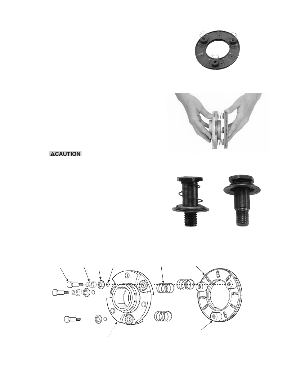
D. Assembling the Armature and Hub
Assemble the armature to the armature hub with the
autogap mounting accessory. The hub is reversible.
The side on which the armature is mounted will
depend on the direction in which the taperlock bush-
ing must enter.
The autogap assembly is a double spring device
which allows for automatic armature clearance and
adjustment for wear. The smaller or conical spring
pushes the
ar ma ture from the rotor face, leaving a
gap of about 1/32 inch, while the straight spring auto-
matically follows up for wear. This combination main-
tains maximum performance ef fi cien cy throughout the
life of the unit.
The assembly procedure for the autogap accessory
is as follows. (Figure 5)
Step 1
Place the straight springs over the armature
bosses on the back side of the armature.
(Figure 6)
Step 2
Place the
armature hub over the
straight springs.
The straight springs must fit into the grooves
in the
armature hub. (Figure 7)
Step 3
Compress the conical springs against the
retainer rings by sliding the detent springs
toward the head of the pins.
(All pins) (Figure 8)
Step 4
Insert the assembled drive pins through the
armature hub and straight springs and into
the threaded armature boss es. Apply grade
Drive Pin
Conical
Spring
Retainer
Detent
Spring
Straight
Spring
Armature
Armature
Hub
Armature
Boss
Figure 5
Figure 6
Figure 7
Figure 8