Warner Electric SFPBC-500, SFPBC-650 User Manual
Page 3
3
Warner Electric • 800-825-9050
P-202-01 • 819-0482
SFC-500 SFC-650
Clutch-Coupling Pin Drive Armatures
The illustration drawings, parts lists, and exploded
views for these units can be found on pages 30, 31 and
34 thru 37.
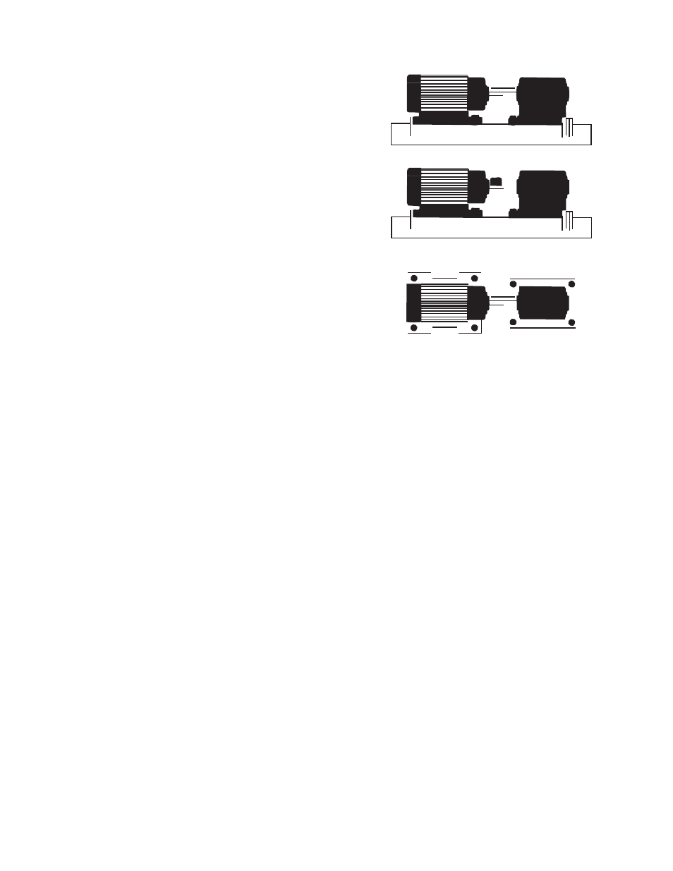
A. Aligning the Shafts
In order for the clutch-coupling unit to operate
properly, the mounting shafts of the motor and
reducer or other hardware must be aligned with respect
to each other before the unit is installed. The two shafts
should be con cen tric with each other within .004 T.I.R.,
and angular alignment should be within 1/2 degree.
(Figure 1)
1.
Use a straight-edge to check if the shafts are
aligned with each other. For a more precise
indication of align ment, use a dial indicator.
2.
Adjust the position of the motor, reducer, or
other hardware as required to achieve the cor-
rect
align ment.
3.
To be sure the shafts stay in alignment, drill
holes for tapered dowel pins through the
mounting bases of the motor, reducer, or other
hardware and into the mounting surfaces. This
procedure will ensure that, after the clutch-cou-
pling has been installed, the shafts can easily
be placed in proper alignment again by lining
up the holes and secured by inserting the dow -
el pins.
B. Installing the Conduit Box
Install the conduit box on the field. Instructions for this
procedure are supplied with conduit box.
C. Mounting the Field-and-Rotor Assembly
Either the field-and-rotor assembly or the
armature-and-hub assembly can be installed first,
depending on the char ac ter is tics of each application.
The SFC-500 clutch-couplings are bearing-mounted
units. The SFC-650 units are either bearing-mounted or
flange-mounted.
Figure 1
Bearing Mounted Units
In bearing-mounted units, the field and rotor are
shipped as an assembly. Step 1 applies only to the
SFC-650 units. Steps 2-5 apply to both the SFC-650
and SFC-500.
1.
The SFC-650 field and rotor assemblies are
mounted on the shaft with a taperlock bushing.
Insert the bush ing into the ta pered bore, lining
up the clearance holes in the bushing flange
with the tapered holes in the rotor hub.
2.
Insert a key into the keyway in the bore of the
rotor and slide the assembly onto the shaft.
3.
If the armature has been secured to the shaft
first, then adjust the rotor’s position to allow
ap prox i mate ly 1/32-inch between the two faces.
(Figure 11)
4.
Secure the assembly on the shaft by alternately
tight en ing the two screws.
5.
A tab or torque arm is provided to prevent the
field from rotating with the shaft. Insert either a
pin in the U-slot or a fork around the torque arm
to prevent this rotation. Under no circum-
stances, however, should the field be so tightly
restrained that is preloads the bearing. For more
information on torque tabs, see page 18.