Sfpbc-500 clutch/brake coupling normal duty – Warner Electric SFPBC-500, SFPBC-650 User Manual
Page 38
38
Warner Electric • 800-825-9050
P-202-01 • 819-0482
1
(Shipped
Assembled)
8
1-3
1-2
1-4
1-5
1-1
2
3
4
5
2
7B
7C
6B
7B-1
7C-1
8
8
7A-1
7A
6A
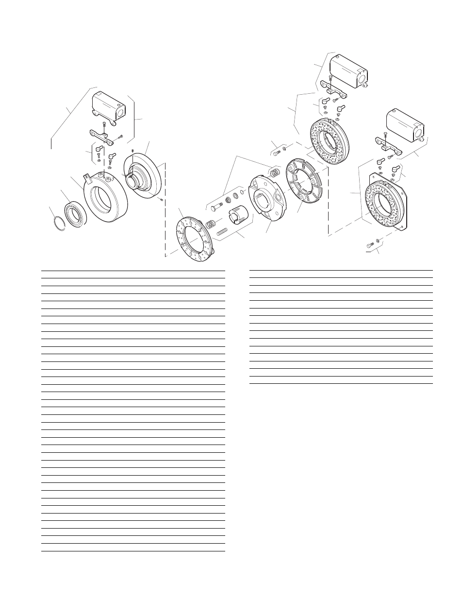
SFPBC-500 Clutch/Brake Coupling
Normal Duty
Item
Description
Part Number
Qty.
1
Field and Rotor Assembly
1
6 Volt – 3/4" Bore
5200-452-002
24 Volt – 3/4" Bore
5200-452-004
90 Volt – 3/4" Bore
5200-452-005
6 Volt – 7/8" Bore
5200-452-008
24 Volt – 7/8" Bore
5200-452-010
90 Volt – 7/8" Bore
5200-452-011
90 Volt – 15/16" Bore
5200-452-017
6 Volt – 1" Bore
5200-452-020
24 Volt – 1" Bore
5200-452-022
90 Volt – 1" Bore
5200-452-023
6 Volt – 1-1/8" Bore
5200-452-026
24 Volt – 1-1/8" Bore
5200-452-028
90 Volt – 1-1/8" Bore
5200-452-029
6 Volt – 1-1/4" Bore
5200-452-032
90 Volt – 1-1/4" Bore
5200-452-035
1-1
Rotor
1
3/4" Bore
5200-751-002
7/8" Bore
5200-751-003
15/16" Bore
5200-751-004
1" Bore
5200-751-005
1-1/8" Bore
5200-751-006
1-1/4" Bore
5200-751-007
1-2
Field
1
6 Volt
5200-451-002
24 Volt
5200-451-004
90 Volt
5200-451-005
1-3
Terminal Accessory
5311-101-001
1
1-4
Ball Bearing
166-0110
1
1-5
Retainer Ring
748-0002
1
2
Armature
5300-111-002
2
3
Autogap Accessory
5200-101-009
6
4
Bushing* - 1/2" to 1-1/4" Bore
180-0116 to 180-0128 1
5
Armature Hub
5300-541-004
1
6A
Mounting Accessory - I.M.
5102-101-001
2
6B
Mounting Accessory - O.M.
5300-101-008
1
Item
Description
Part Number
Qty.
7A
Magnet - I.M.
1
6 Volt
5300-631-002
24 Volt
5300-631-003
90 Volt
5300-631-005
7A-1
Terminal Accessory
5311-101-001
1
7B
Magnet - O.M. - Offset
1
90 Volt
5300-631-014
7B-1
Terminal Accessory
5311-101-001
1
7C
Magnet - O.M. - Flush
1
6 Volt
5300-631-009
24 Volt
5300-631-010
90 Volt
5300-631-011
7C-1
Terminal Accessory
5311-101-001
1
8
Conduit Box
5200-101-010
2
* See page 44 for specific part numbers.
How to Order:
1.
Specify Bore Size for Item 1 and Item 4.
2.
Specify Voltage for Item 1 and Item 7A, 7B
or 7C.
3.
Specify Inside Mounted for Item 7A and
Outside Mounted (Offset) for Item 7B or
Outside Mount ed (Flush) for Item 7C.
Example:
SFPBC-500 Clutch Brake Cou pling per I-25546 - 90
Volt, Inside Mounted, 1" Bore
These units, when used in con junc tion with the cor-
rect Warner Electric conduit box, meet the standards
of UL508 and are listed under guide card #NMTR, file
#59164.
These units are CSA certified under file #LR11543.