Warner Electric SFPBC-500, SFPBC-650 User Manual
Page 12
12
Warner Electric • 800-825-9050
P-202-01 • 819-0482
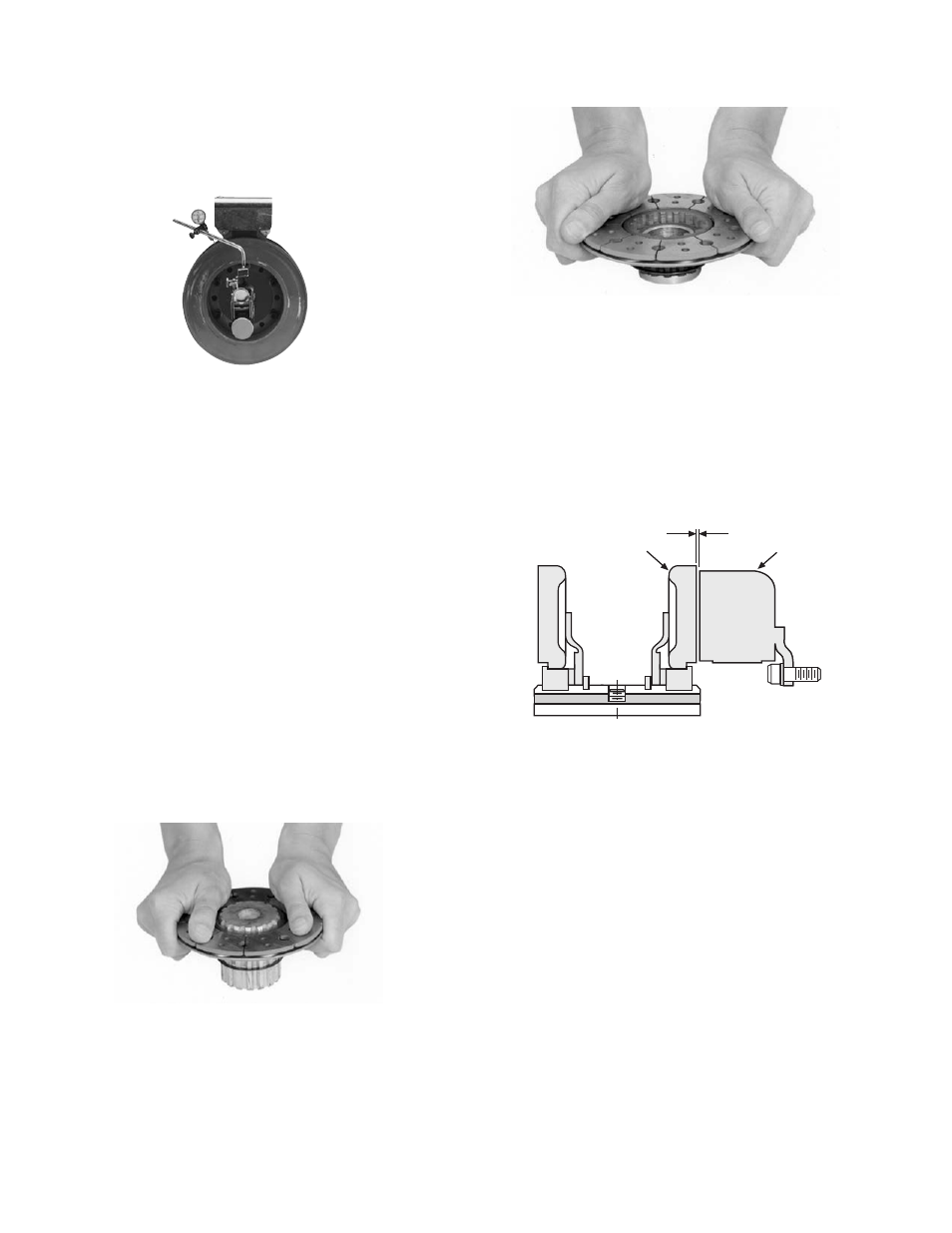
Figure 6
4.
Use a dial indicator to check the unit for
con cen tric i ty and squareness to the
shaft. The unit should be concentric within
.010 T.I.R. and square within .006 T.I.R. (Figure
4)
D. Assembling the Hub and Armatures
The heavy duty units contain spline drive armatures
and hubs. The armatures are shipped with a built-in
autogap spring accessory. This device automatically
maintains a gap of about 1/32'' between the armature
and magnet faces for the life of the unit.
Use the following method to assemble the armature
and splined hub:
1.
Place the armature hub up on one end.
2.
Check the detent ring in the armature
assembly to make sure it is evenly centered
around the spline. This ring moves freely, and
it should be centered for eas i er assembly of
the hub.
3.
Holding one of the armatures with the
segmented side up, press the armature on to
the hub using firm back-and-forth pressure.
(Figure 5)
4.
Push the assembly up against the retainer
ring.
Figure 4
5.
Turn the hub over and repeat Steps 3 and 4
with the other armature. (Figure 6)
E. Mounting the Armature-Hub Assembly
1.
Insert a key in the keyway of the hub and
slide the armature-hub assembly on to the
shaft.
2.
Position the assembly so that the face of the
ar ma ture is about 1/32-inch from the magnet
face. (Figure 7)
3.
Secure the armature-hub assembly in this
position by tightening the two setscrews in
the hub.
4.
Check the assembly by pressing the armature
into contact with the magnet face and then
Figure 5
1/32 inch Gap
Magnet
Armature
Figure 7