Warner Electric SFPBC-500, SFPBC-650 User Manual
Page 16
16
Warner Electric • 800-825-9050
P-202-01 • 819-0482
(Figure 10)
Step 6
Tighten these drive pins until shoulders of
pins are against face of armature bosses.
Since threads are class No. 3 fit, pins may
seem to bind.
Note:
Alternately tighten each drive pin a
few turns at a time.
Step 7
Repeat Steps 5 and 6 for the second
amature. (Figure 11)
Step 8
Compress the armature hub and one of the
armatures together until the armature hub
bottoms on the armature boss. Slide the
retainer on each pin down tightly against
the armature hub. (Figure 12)
Step 9
Turn the assembly over and repeat Step 8
for the second armature.
Note:
This position must not be disturbed
during com ple tion of the assembly.
(Figure 13)
E. Mounting the Armature Assembly
The armature and armature hub are mounted on the
shaft with a taperlock bushing. All parts must be clean
and free from burrs and chips before assembling.
1.
Place the bushing into the hub and insert the
key. The key is a side-to-side fit and should
not contact the top of the keyway.
2.
Insert the locking setscrews loosely into the
bushing and slide the assembly onto the
shaft.
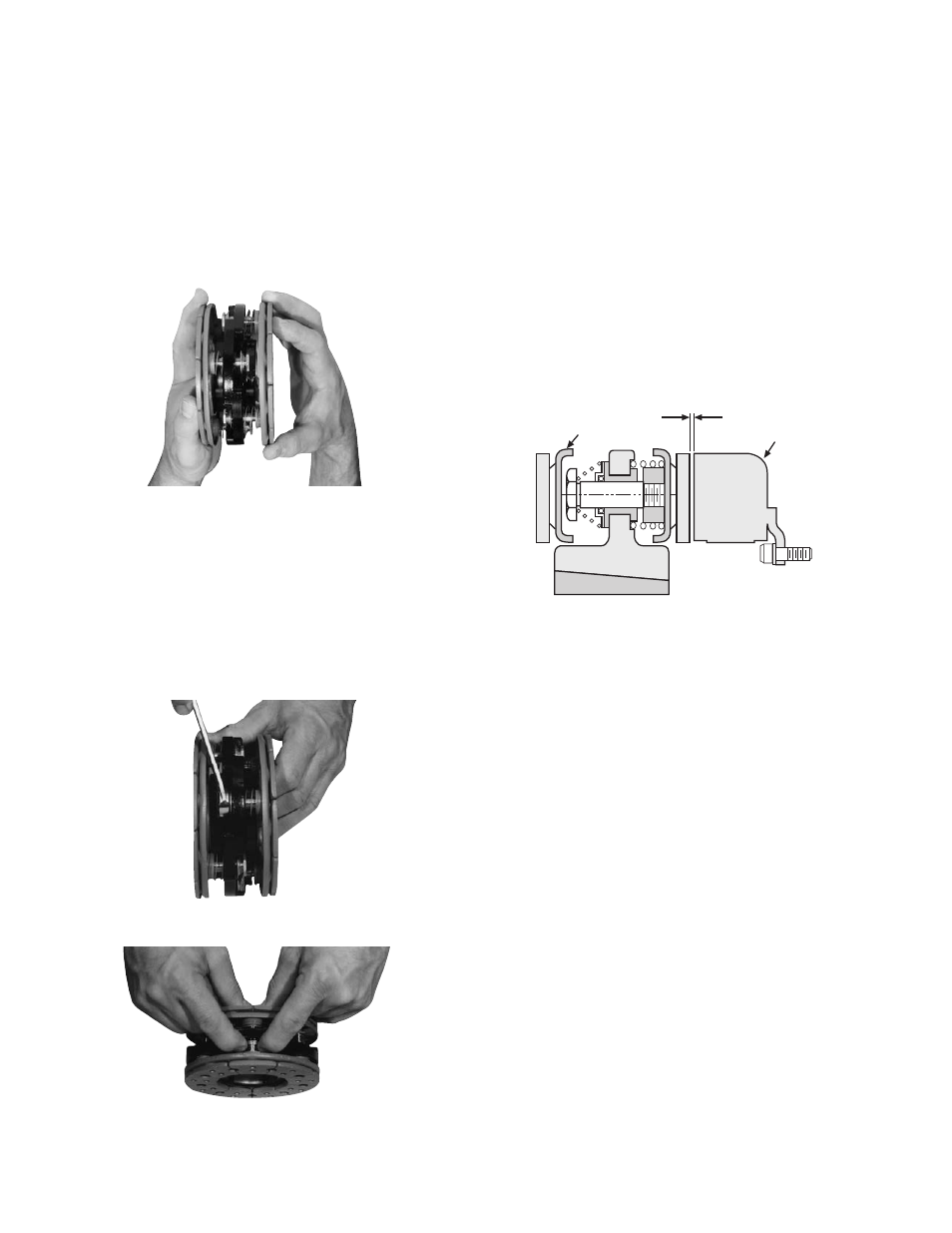
3.
Place the face of the armature approximately
1/32'' from the face of the magnet. Once this
gap is set, it will be automatically maintained
throughout the life of the unit. (Figure 14)
4.
Secure the armature’s position on the shaft
by al ter nate ly tightening each setscrew.
During the tight en ing process the bushing
Figure 11
Figure 12
Figure 13
Armature
1/32 inch Gap
Magnet
Figure 14