Warner Electric SFPBC-500, SFPBC-650 User Manual
Page 11
11
Warner Electric • 800-825-9050
P-202-01 • 819-0482
This illustration drawing, parts list, and exploded
view for this unit can be found on page 40 and 41.
A. Aligning the Shafts
In order for the clutch-coupling unit to operate
properly, the mounting shafts of the motor and the
reducer or oth er hardware must be aligned with
respect to each other before the unit is installed.
The two shafts should be con cen tric with each
other
within 004 T.I.R., and angular align ment
should be within 1/2 degree.
1.
Use a straight edge to check if the shafts
are aligned with each other. For a more pre-
cise indication of align ment, use a dial indi-
cator.
2.
Adjust the position of the motor, reducer, or
other hardware as required to achieve the
correct align ment.
3.
To be sure the shafts stay in alignment, drill
holes for tapered dowel pins through the
mounting bases of the motor, reducer, or
other hardware and into the mounting
surfaces. This procedure will ensure that,
after the clutch-coupling has been installed,
the shafts can easily be placed in proper
alignment again by lining up the holes and
secured by inserting the dow el pins.
B. Installing the Conduit Boxes
Install a conduit box on the brake magnet and on
the clutch field. Instructions for this procedure are
supplied with a conduit box.
SFPBC-500 Spline Drive Armature
Clutch/Brake Coupling
Figure 1
C. Mounting the Magnet
The brake half of the clutch/brake unit is usually
installed first; however, in some cases it may be nec-
essary to start with the clutch portion of the unit to
assure a
proper as sem bly when complete.
The brake magnet is mounted to a stationary machine
member by a flange. Extreme care must be taken in
se lect ing the location for the mounting of the magnet.
Prop er positioning is very important for the unit to
function cor rect ly.
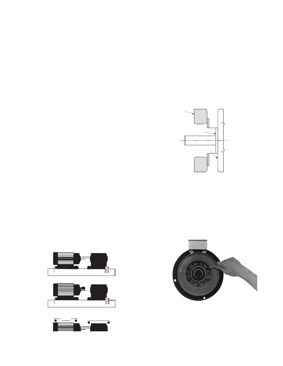
1.
A pilot diameter on the mounting surface is
essential to hold the magnet within the
required tolerances. (Figure 2)
2.
A machined pilot diameter is provided on the
magnet mounting flange (refer to illustration
drawings page 40) to aid in the proper
positioning of the magnet.
3.
Once the mounting surface has been pre-
pared, the magnet is bolted in place with cap-
screws and lockwashers. (Figure 3)
Field
Pilot Diameter
Mounting Surface
Figure 2
Figure 3