IAI America PDR-101-MW User Manual
Page 71
61
The resolution of the output pulse trains is determined by the electric gear ratio of the command pulse input
set in the position control parameters, and the pulses are output with the same resolution as the command
signal.
These pulse signals can be disabled with the PIO function setting flag explained in (1). Disable them if
pulse feedback is not used.
z
Set the same positive/negative logic as for the command pulse input mode (CPMD) regardless of
whether these signals are used or not.
z
Set these signals in such a way that there are no logical contradictions if you import them in the host
controller to configure a closed loop.
(28) Speed Loop Gain
Name Symbol Unit Input
range
Default value
(reference)
Speed loop gain
VLPG
-
10~10000
[A]
Set the gain of the speed control loop.
An appropriate value corresponding to the applicable actuator has been set at shipment from the factory.
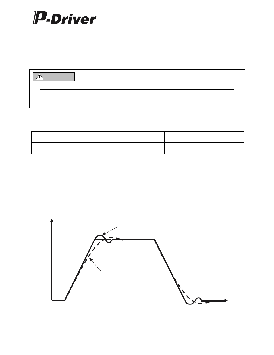
This parameter determines the response of the speed control loop. Set a larger value to make the control
loop follow the speed command signals more aggressively (the servo rigidity increases). Make the setting
value higher for larger load inertial ratios. Note, however, that over-shoot and oscillation tend to occur if the
setting value is made too large, causing vibrations to be generated in the mechanical parts of the system.
If the setting value is high (over-shoot)
If the setting value is low
Speed
Time
Caution