2 name and function of each part of the controller – IAI America PDR-101-MW User Manual
Page 12
2
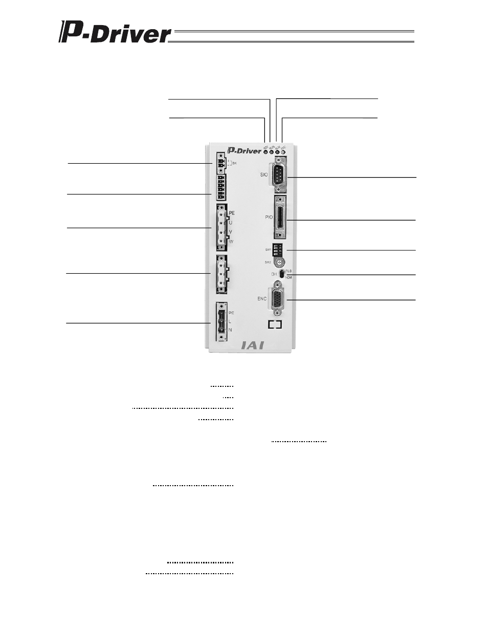
1.2 Name and Function of Each Part of the Controller
(1) Input connector for main power supply
Connects the power supply.
(2) Connector for regenerative resistance unit Connects a regenerative resistance unit (optional).
(3) Motor connector
Connects the actuator’s power cable.
(4) Input connector for actuator sensor
Connects cables from the actuator’s sensors such as
LS, CREEP and OT (optional).
(5) Input connector for electromagnetic-brake power supply
Connects the power supply for electromagnetic brake.
(An electromagnetic brake requires an external power
supply.)
(6) Status indicator (LED)
Used to monitor the controller’s operating condition.
RDY (green): Indicates that P-Driver is operating
normally.
RUN (green): Indicates that the servo is on.
ALM (red):
Indicates that an alarm is generated.
ENC (yellow): Indicates that the encoder is
disconnected or not connected.
(7) Communication connector
Connects the PC software cable.
(8) I/O signal connector
Connects the control I/O signals.
ALM (red)
ENC (yellow)
RUN (green)
RDY (green)
(6) Status indicator LED
(5) Input connector for
electromagnetic-brake power supply
(4) Input connector for actuator sensor
(optional)
(3) Motor connector
(2) Connector for regenerative
resistance unit (optional)
(1) Input connector for main power
supply
(7) Communication
connector
(8) I/O signal connector
(9) System
setting
switch
(10) Brake release switch
(11) Encoder brake connector