3 noise elimination measures and grounding – IAI America ACON-CG User Manual
Page 36
22
3. Installation and Noise Elimination
3.3
Noise Elimination Measures and Grounding
The following explains the noise elimination measures that should be taken when using this controller.
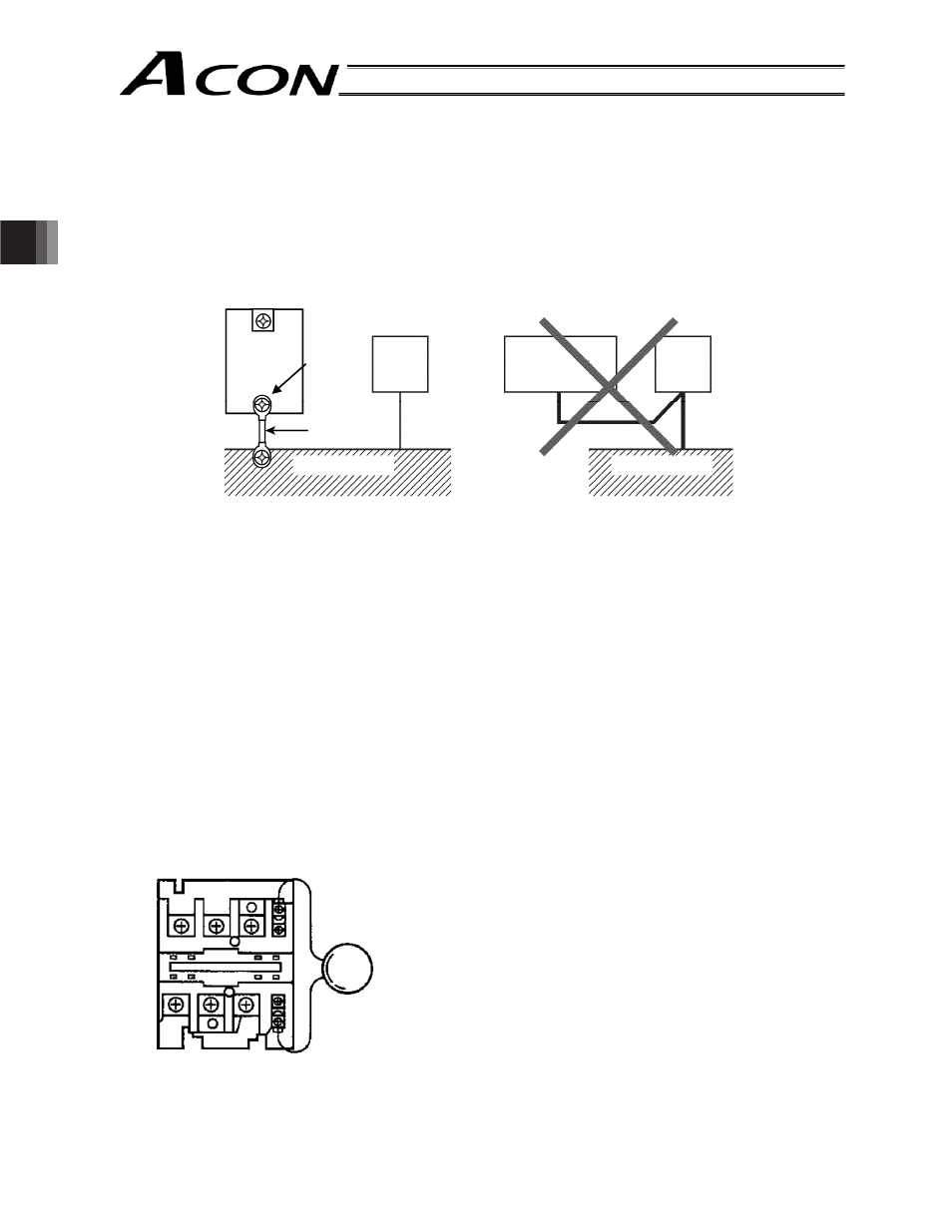
(1) Wiring and power supply connection
[1]
Grounding must be made by ground resistance of 100
7
Moreover, the thickness of cable shall be 1.6 mm or thicker.
2
[2]
Precautions regarding wiring method
Use a twisted cable for connection to the 24 VDC external power supply.
Separate the controller cables from high-power lines such as a cable connecting to a power circuit.
(Do not tie them together or place in the same cable duct.)
When extending the supplied motor cable or encoder cable, consult IAI’s Technical Support.
(2) Noise sources and elimination
Noise from these sources can be eliminated by implementing the measures specified below.
[1]
AC solenoid valves, magnet switches and relays
Measure: Install a noise absorber in parallel with the coil.
Å
Noise absorber
Controller
Other
equip-
ment
Controller
Other
equip-
ment
Connect a cable of the
largest possible size
over the shortest
possible distance
Ground resistance of 100
7 or less
Ground terminal
Ground terminal
Connect the
ground line to
the mounting
screw of the
main unit.
Do not link or connect the ground line
with other devices; ground it for each
controller.
Noise generates from many sources, but the most common sources of noise you should consider when
designing a system are solenoid valves, magnet switches and relays.
Connect to each coil over the shortest possible wiring distance.
When a noise absorber is installed on the terminal block, etc., its
noise elimination effect will decrease if the distance from the coil
is long.
is long.