Wiring diagrams – E-Mon E-PS-E-RTU-N User Manual
Page 24
Chapter 2 Installation
Electrical Installation
24
PowerSmart+ Power Quality Meter
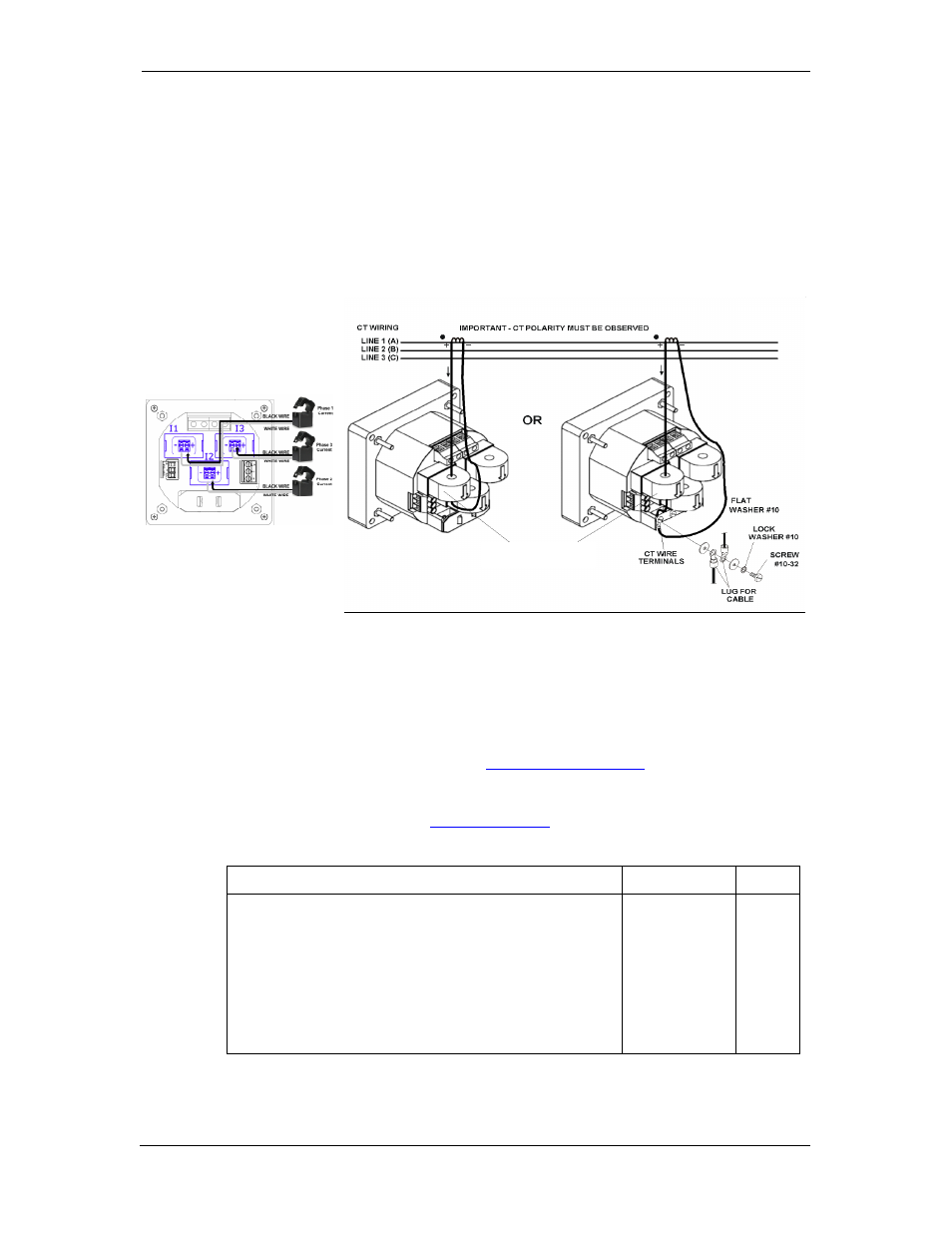
To connect the internal CT to the high current external CT, pass the
external CT wire through the meter CT core, see Figure 2-8a
for details
and observe the arrow that indicates the current direction.
In case of a retrofit application where each external CT ends with two
wires:
1. Pass one wire through the meter CT core.
2. Connect the wire to one of the meter termination screws.
3. Connect the second wire from the external CT to the termination
screw to close the loop.
Internal Current Transformer
With highly Accurate external
Current Transformer
Figure 2-8 Current Input Connection
Wiring Diagrams
For AC input ratings, see
Technical Specifications
in Appendix A for more
details.
Table 2 presents the available wiring configurations in the meter. For
more details, see
Basic Meter Setup
in Chapter 5.
Table 2: Wiring Configurations
Wiring Configuration
Setup Code
Figure
3-wire 2-element Delta direct connection using 2 CTs
3dir2
2-8
4-wire 3-element Wye direct connection using 3 CTs
4Ln3 or 4LL3
2-9
4-wire 3-element Wye connection using 3 PTs, 3 CTs
4Ln3 or 4LL3
2-10
3-wire 2-element Open Delta connection using 2 PTs, 2 CTs
3OP2
2-11
4-wire 2½-element Wye connection using 2 PTs, 3 CTs
3Ln3 or 3LL3
2-12
3-wire 2½-element Open Delta connection using 2 PTs, 3 CTs
3OP3
2-13
4-wire 3-element Delta direct connection using 3 CTs
4Ln3 or 4LL3
2-14
3-wire 2½-element Broken Delta connection using 2 PTs, 3 CTs 3bLn3 or 3bLL3
2-15