A7.0 appendix – Electronics International MVP-50P User Manual
Page 82
Page 1 of 3
A7.0 Appendix:
Setting Up the MVP to Monitor and Display an Annunciator
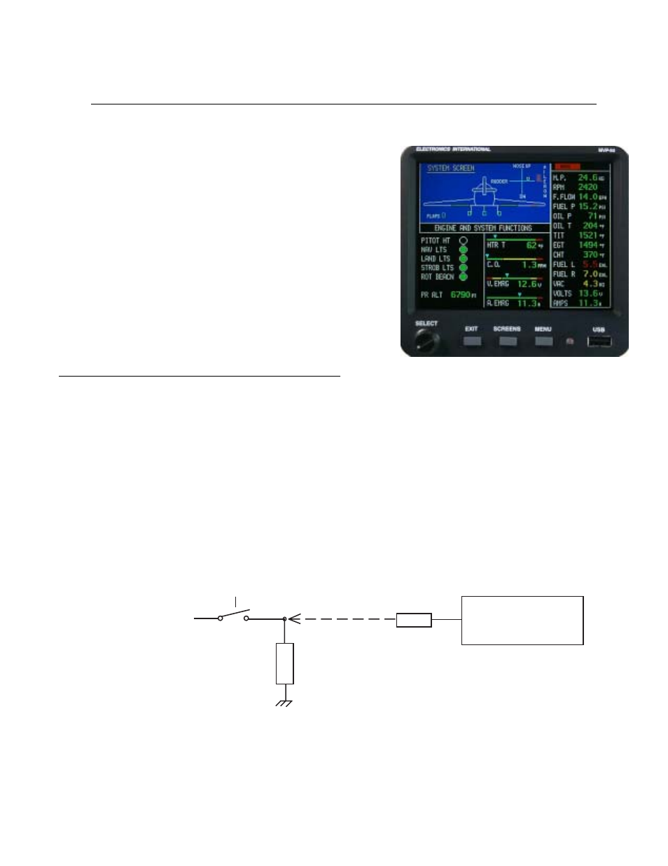
An Annunciator is displayed as a single light on the MVP. It can
be used to show the status of a function such as the Boost Pump,
Pitot Heat, Canopy Latch, Nav Lights or just about any function in
the aircraft. When an Annunciator is on, it will be displayed with
one of the following colors: Green, Yellow, Red, Pink, Blue or
Orange. When an Annunciator is off, it will be displayed as black.
If Red or Yellow is selected for the color, a voice warning can be
provided and the Annunciator can be set to blink until it is
acknowledged.
An Annunciator is normally shown in an ON or OFF condition. It
can be set to display different colors for various voltage levels.
1.0 Interface the Annunciator to the EDC:
Any Temperature or Resistive Fuel Level Channel on the EDC may be used to monitor the state of a switch, relay
or output from a device. The output must be a voltage that changes when the state of the function changes (from off
to on).
To monitor a voltage, a VI-221 (Voltage Interface Unit) is required. This consists of a 221K ohm resistor heat
shrunk between two wires with a D-Sub pin crimped on one end. The following methods may be used to interface
an EDC channel to a switch, relay or device:
A. Monitoring a Signal That Switches Between Any Voltage and Ground:
EDC
Temp or Resistive Fuel
Level Channel.
Device, Switch or Relay
Bus or any Voltage
Load
VI-221